
-
-
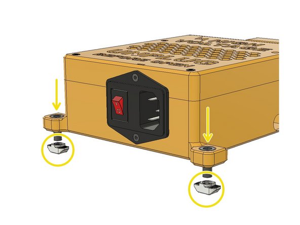
Insert two M3 Hex Nuts to the back slots of the PSU housing body.
-
Mount the SSR module with M3 x 8mm Screws. The orientation of the SSR is important for cable management. Please position as seen on the picture.
-
Place the WAGO 3pin Terminals to their slots in the PSU Body. You should feel a slight click when you push them.
-
-
-
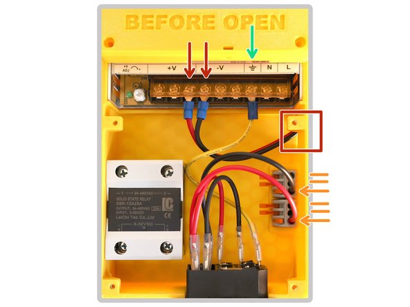
Pass the Octopus Pro controller's 24v power cable through the side hole and connect it to the V+ and V- ports on the PSU. Red cable should be connected to + Red/Black cable should be connected to -
-
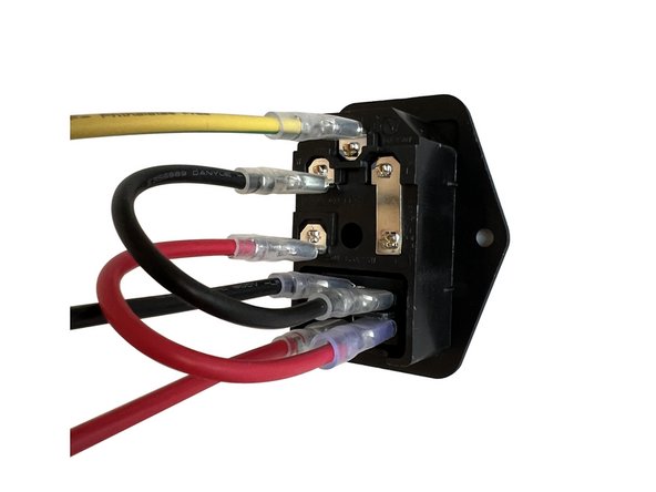
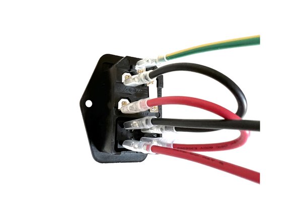
Connect the yellow GND cable coming from Power Socket to the Ground port on the PSU.
-
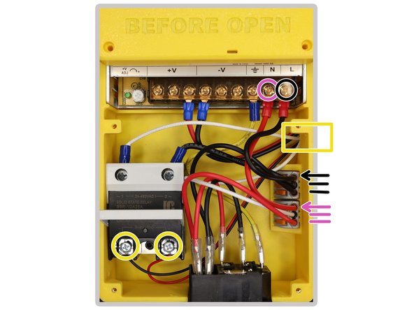
Insert the crimped cable ends to the WAGO connectors as seen in the picture and lift down the orange levers to lock them.
-
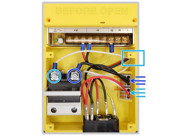
Pass the Heated Bed Power Cables(28cm) through the side hole of the body and connect the fork crimp terminal to SSR. Connect the other end of the cable to the lower WAGO. This is an AC cable that has no orientation requirement.
-
Connect the other side of the SSR to the upper WAGO with the supplied 10cm cables.
-
Connect the N port on PSU to the WAGO terminal at the bottom with the supplied 10cm cable.
-
Connect the L port on PSU to the WAGO terminal with the supplied 10cm cable.
-
Lastly, pass the Board to SSR Cable through the hole on the side of the body and connect the bottom terminals of the SSR. This cable is a DC cable and orientation is important. Please connect the RED cable to the terminal on the right. (+)
-




Cancel: I did not complete this guide.
3 other people completed this guide.
