
-
-
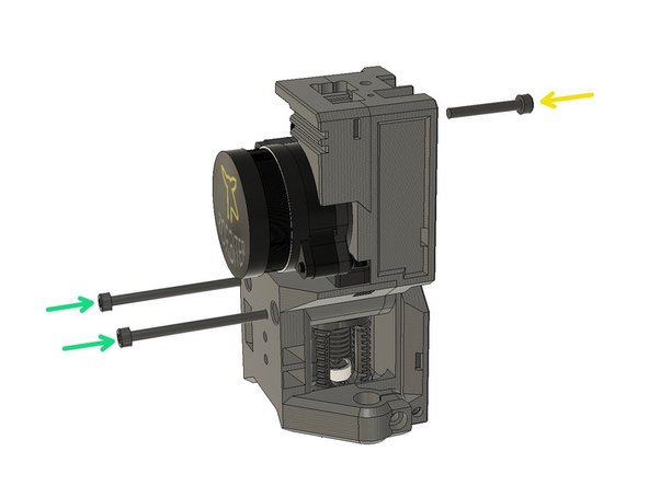
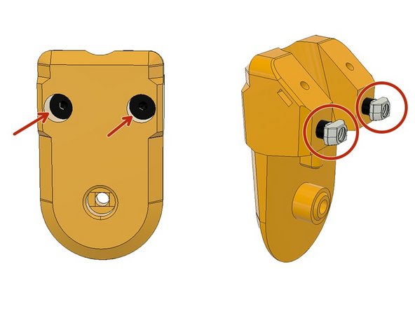
Use the supplied hex key and remove these two screws to disassemble the throat.
-
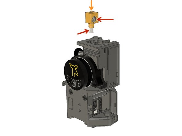
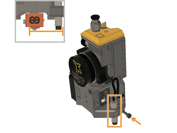
Position the hotend as seen in the picture, insert the Heater Cartridge and tighten the screw to fix it to its place.
-
Insert the Thermistor Cartridge and tighten its screw below. Do not overtighten because the little grub screw touching the heater cartridge to fix it in its place. You may break it if you overtighten it.
-
-
-
Use the M2.5 x 8mm screws that are supplied by the Dragon hotend to mount it to the front extruder cover part.
-
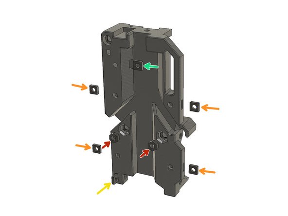
Insert two M3 Square Nuts to the slots on the side. These are for the extruder dock on the front. The dock can be used for future accessories such as input shaper, led lights or a nozzle camera.
-
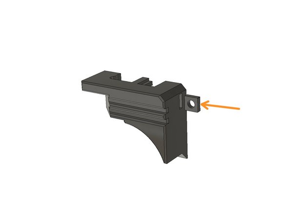
Insert an M3 Square Nut for the Inductive Probe mount.
-
Insert two M3 Square Nuts on the sides for the motor mount. The slot on the left seems impossible however it is pretty easy to push the nut in. Just put the nut into the cable canal, align it with the slot and push it in with a flat screwdriver.
-
Insert a 23.5mm PTFE tube inside the filament way. Align the Orbiter Motor with the PTFE and place it on the front cover.
-
Use two M3 x 8mm screws to mount it to its place.
-
-
-
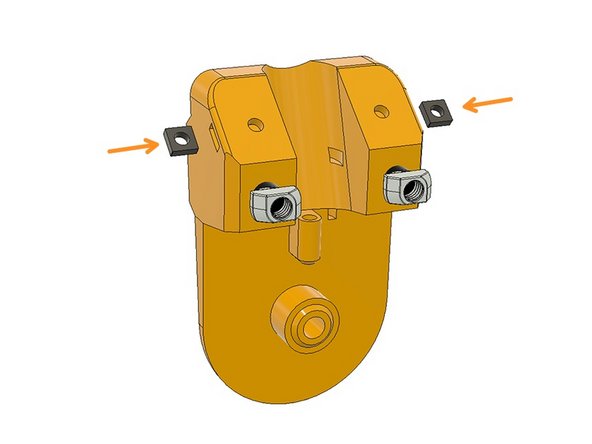
Insert two M3 Hex Nuts in the slots at the back of the Extruder Body. Please use a 25-40 mm M3 screw to push them all the way in by wobbling if necessary.
-
Insert four M3 Square Nuts on the side slots and use a small flat screw drawer to push them all the way in. Ensure the holes are aligned with the slots.
-
Insert an M3 Square Nut into the slot at the bottom. This slot is for the part cooling fan mount.
-
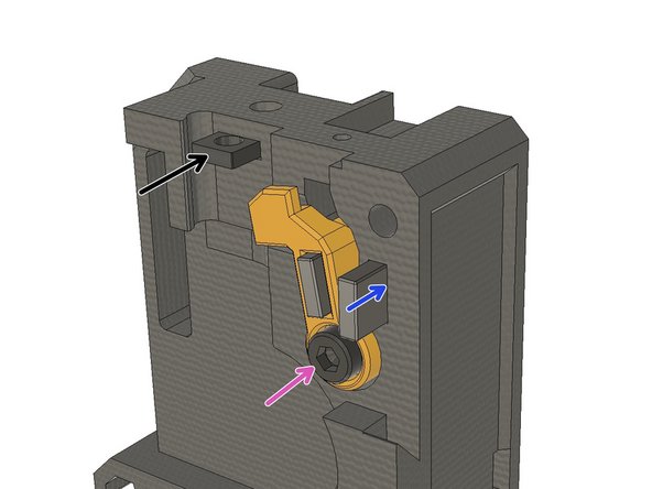
Insert an M3 Square nut for the filament sensor lever.
-
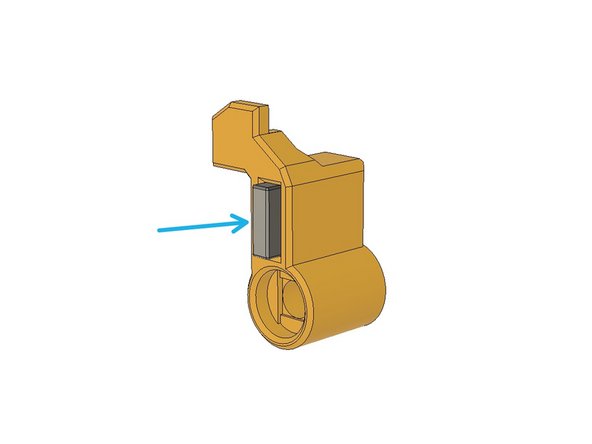
Insert the 10mm - short magnet into the slot on the filament sensor lever.
-
Use an M3 x 16 mm screw to assemble the filament sensor lever.
-
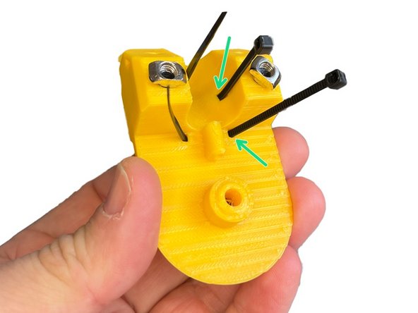
Insert the 20 mm-long magnet into the slot on the extruder body. Magnets should repel each other. Loosen the M3 x 16mm screw until the lever moves freely. Ensure the magnets repelling each other.
-
Insert an M3 Square nut for later assembly of the filament sensor cover.
-
-
-
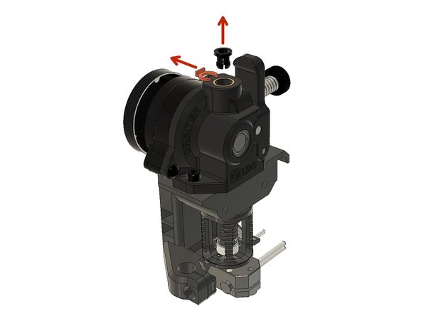
Remove the orange coupler ring and then take out the black bowden coupler.
-
Insert an M3 Square Nut into the slot on the filament sensor lever cover.
-
Fix the filament sensor front cover with an M3 x 22 mm Screw.
-
Use two M3 x 40 mm Screws and combine the body and front cover.
-
-
-
Insert the 12mm PTFE tube under the ball housing. Place the 7mm Steel Ball in its place
-
Push the ball housing into the slot on top of the extruder assembly.
-
Place the filament sensor and fix it with an M2 x 10 mm screw.
-
-
-
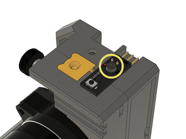
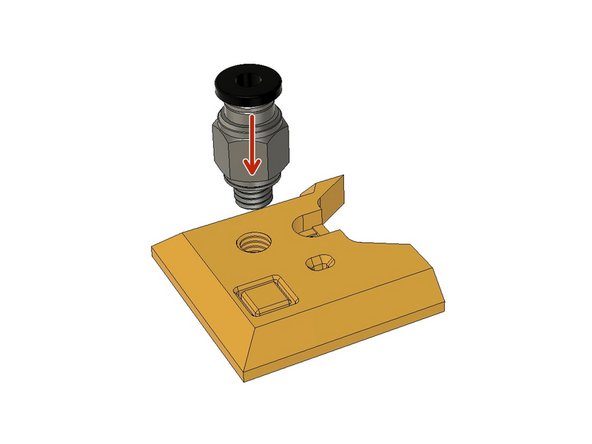
Screw in the PC4 M6 Pneumatic Fitting into the slot on the filament sensor top cover with the button.
-
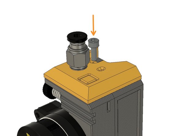
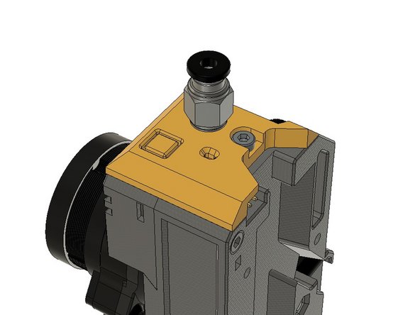
Use an M3 x 8 mm Screw to mount the filament sensor top cover.
-
-
-
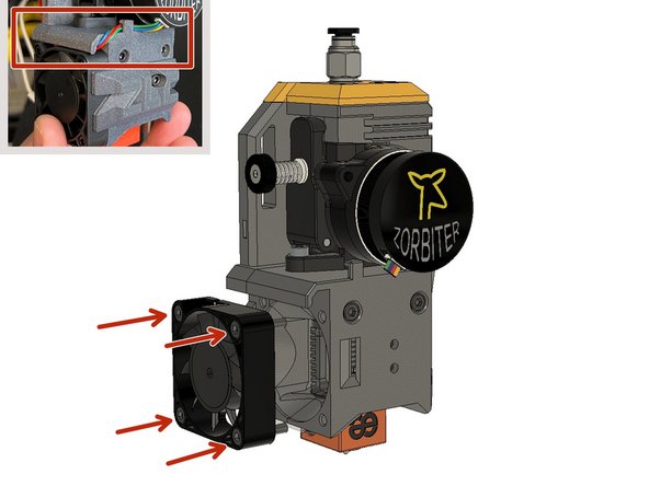
Pass the 40mm Heatbreak Fan cable through the canal and the motor cable behind the bulge and through the canal together with the fan cable. Mount the fan with four M3 x 14 mm Screws.
-
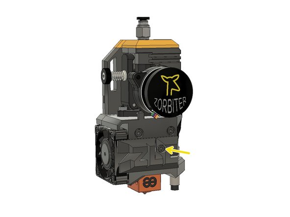
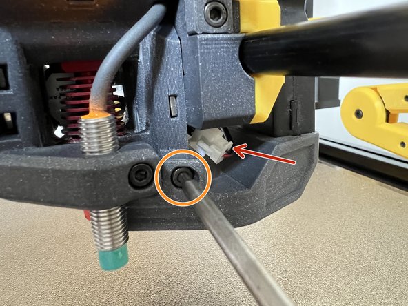
Insert the Inductive Sensor and fasten it with an M3 x 8mm Screw. Align the tip height 1mm above the nozzle level.
-
Position the front logo and screw it in its place with an M3 x 8mm Screw.
-
-
-
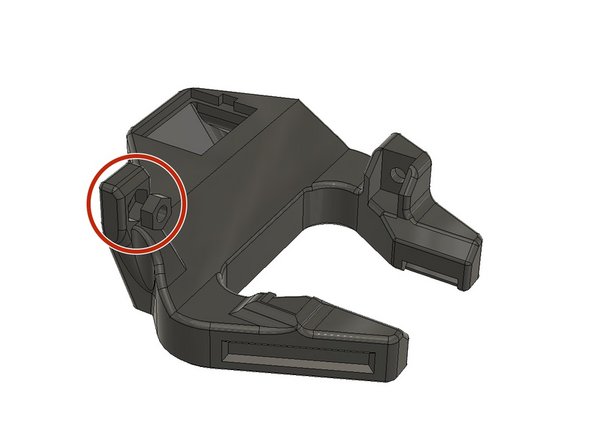
Insert an M3 Hex Nut into the slot on the fan shroud.
-
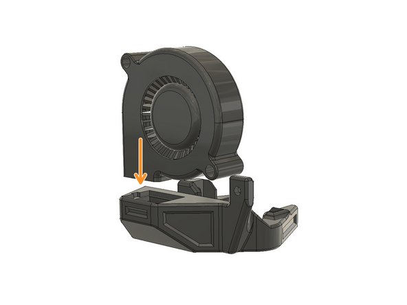
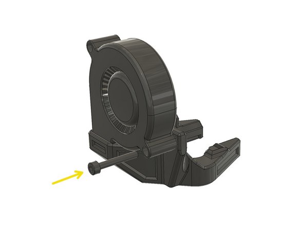
Insert the 5015 Blower Fan into the slot on the fan shroud.
-
Use an M3 x 20 mm Screw to fix the fan on the fan shroud.
-
You will be mounting the blower fan assembly on the extruder later in the following steps.
-
-
-
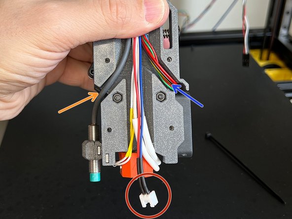
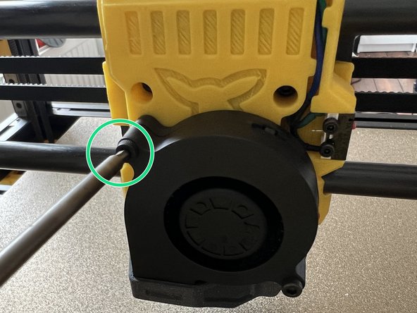
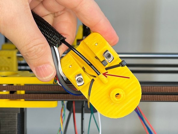
Make sure the motor cable passed behind the bulge and under the cable canal over the extruder fan on the previous step.
-
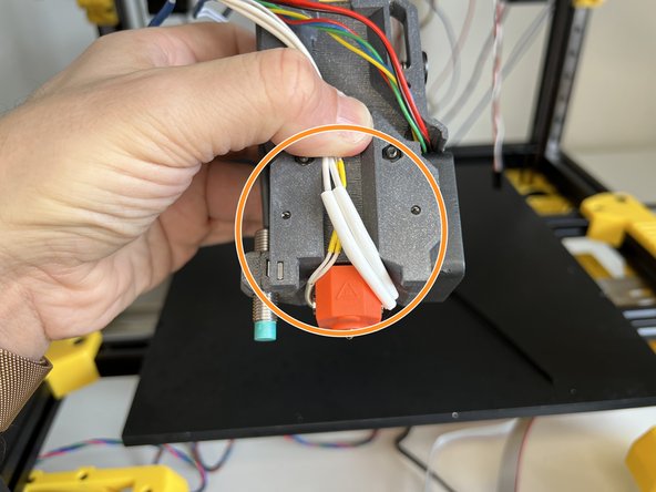
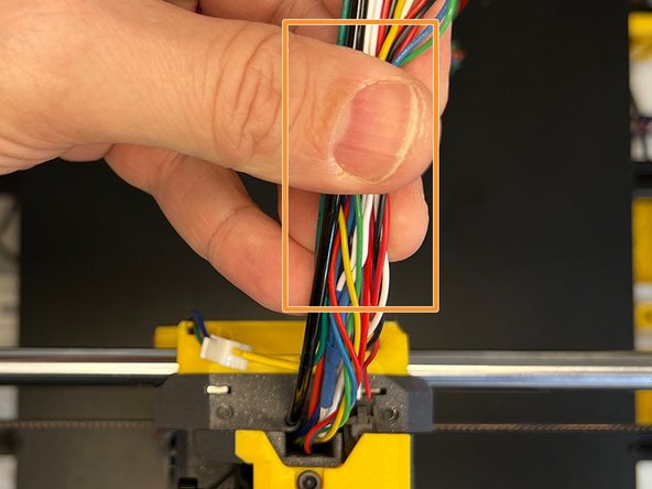
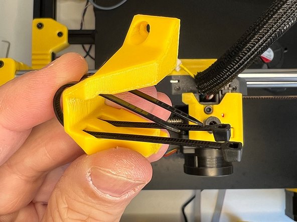
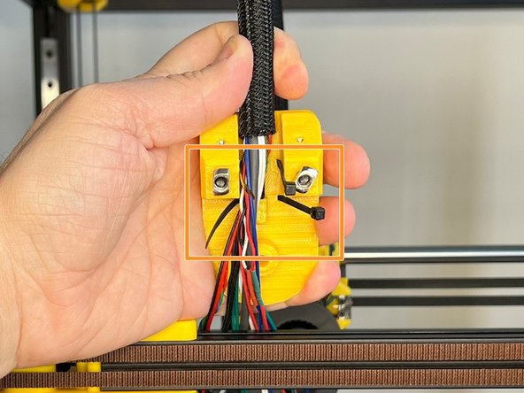
Hold the hotend thermistor and heater cartridge cables as seen in the picture.
-
-
-
Add the 5015 Blower Fan cable to the harness.
-
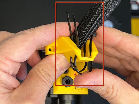
Pass the Inductive Sensor cable through the canal at the back of the extruder body. Ensure to leave some space on the sensor cable to be able to adjust the height of it later.
-
Pass the stepper motor and heatbreak fan cables through the canal.
-
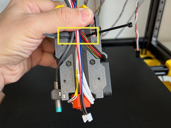
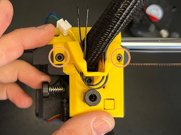
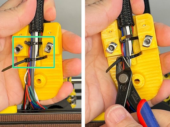
Pass a zip tie behind the cable harness.
-
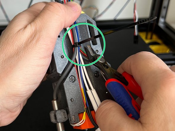
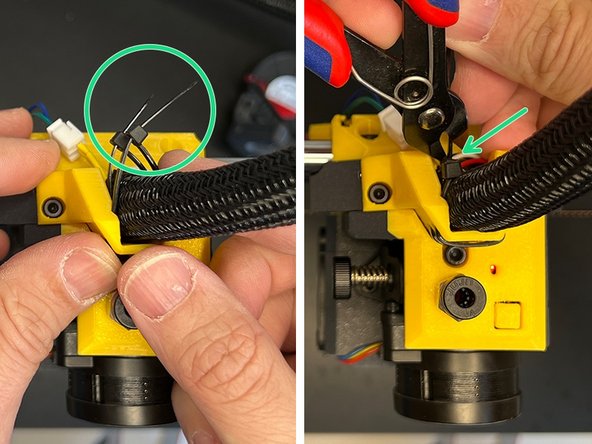
Zip it and cut the excessive part.
-
-
-
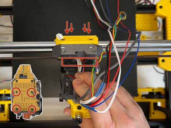
Insert four M3 x 22 mm Screws from the backside of the X carriage and while holding the cable harness, align the bottom two screws with the holes on the extruder body and screw those two bottom screws first. Ensure that the cables are aligned with the vertical harness gap.
-
Now tighten the upper screws. The screw distances are precise, depending on your printer the plastic part may have less tolerance. Press and squeeze with your hand from the front if necessary while tightening.
-
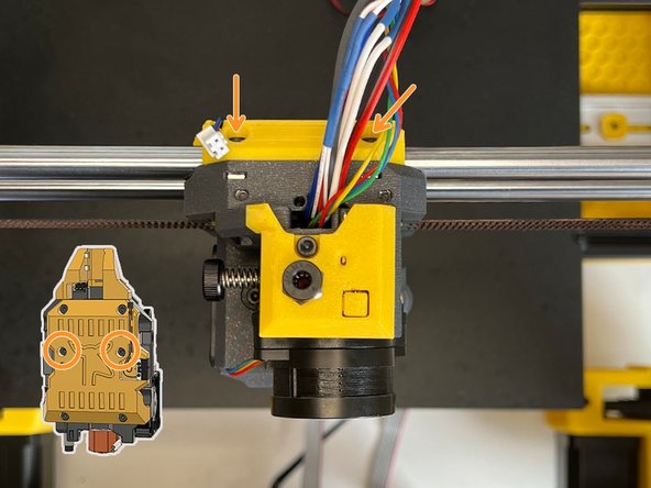
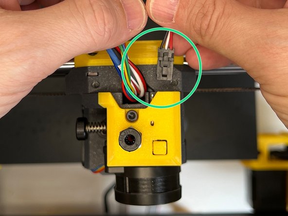
Connect the X-Axis Endstop Sensor and add its cable to the harness.
-
-
-
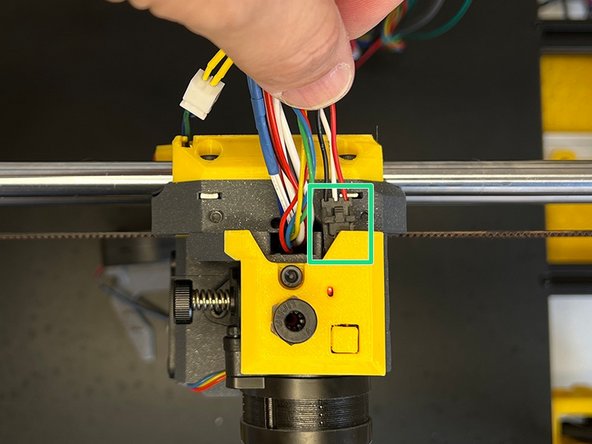
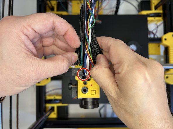
Insert the Zaribo Filament Sensor connector and add its cable to the harness. If there is a rib behind the connector, feel free to trim it with a cutter. Some connectors might have a small rib at the back.
-
Collect the cables and prepare for the sleve.
-
-
-
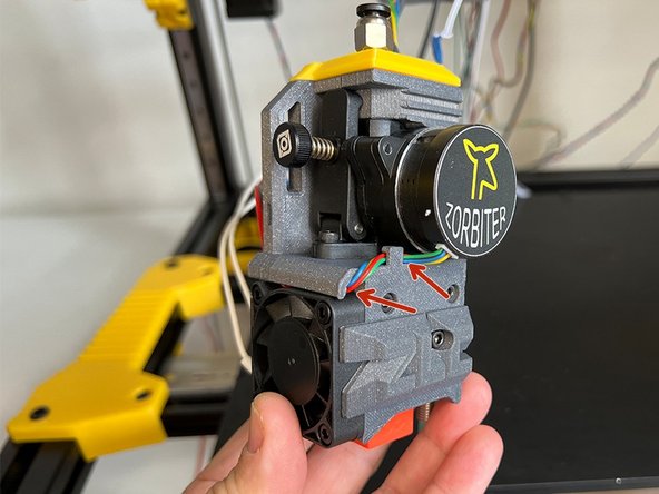
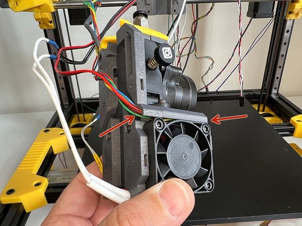
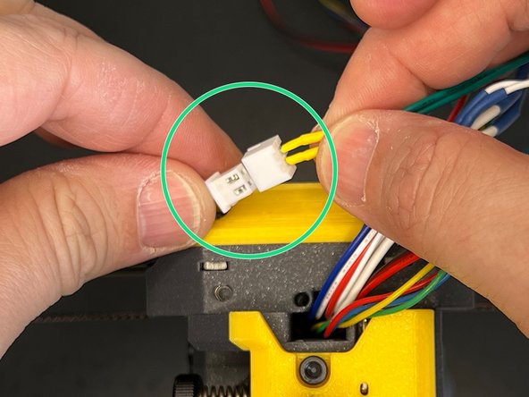
First, connect the 2pin connectors for the blower fan.
-
Use an M3 x 8mm Socket Cap Screw to mount the fan shroud.
-
Lastly, use an M3 x 20mm Socket Cap Screw and fix the fan at the back of the X Carriage.
-
-
-
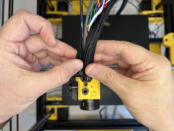
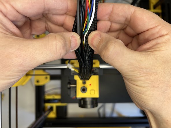
Insert the 3mm nylon filament and tuck the cable harness in the cable sleeve.
-
-
-
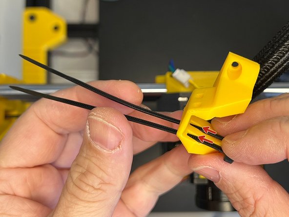
Insert two zip ties through the slots on the Cable Harness Holder.
-
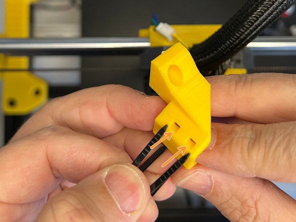
Insert the zip ties through the other two slots in the front.
-
-
-
Tuck in the cable sleeve between the zip ties.
-
Fix the cable holder with two M3 x 8 mm Screws.
-
Zip the ties and cut the excessive parts.
-
-
-
Insert two M5 x 10 mm Screws and screw on the M5 2020 Drop-in T-Nuts Leave 4mm space between the plastic and nut.
-
Insert two M3 Square Nuts on the sides.
-
Insert two Zip Ties to the slots on the back.
-
-
-
Insert the 3mm Nylon Filament's end into the hole on the Z Lift's top part.
-
Pass the cables between the zip ties.
-
Zip the ties and cut the excessive parts.
-
-
-
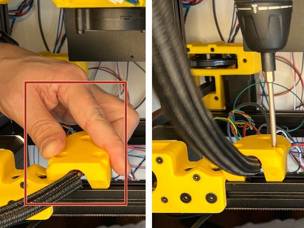
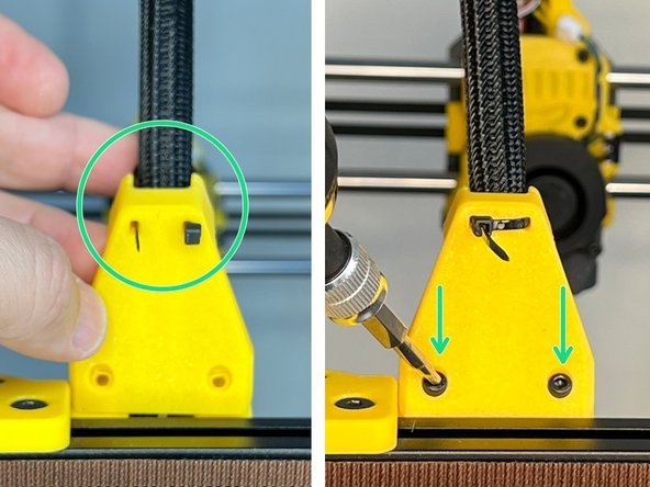
Place the Z Lift Top Part on the 2020 extrusion and screw the M5 x 10 mm Screws to fix it in its place.
-
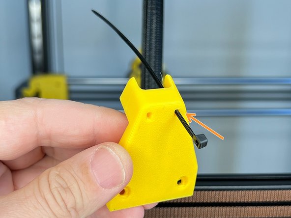
Insert a Zip Tie on the slot of the cable harness support part.
-
Pass the Zip Tie around the cable sleeve and insert it into the second slot on the support part. Please DO NOT TIGHTEN THE ZIP TIE now. Use two M3 x 6 mm Screws to mount the cable support.
-
-
-
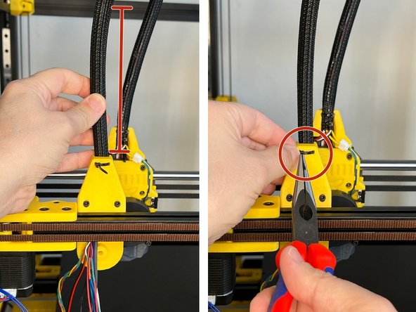
Ensure the cable sleeve stands vertical and then tighten the zip tie. Use a plier if necessary to better tighten.
-
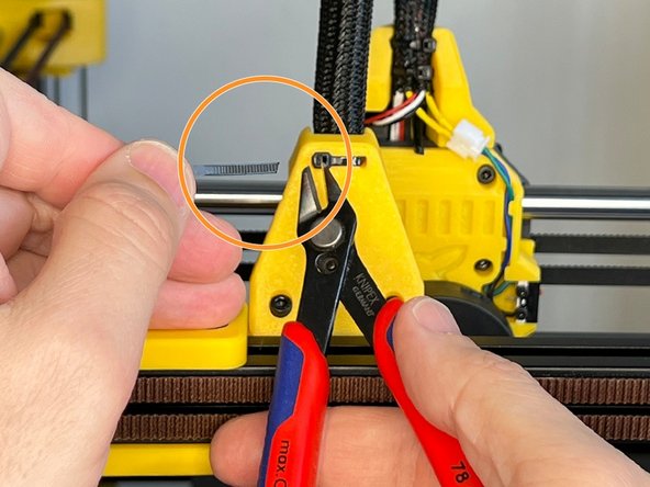
Cut the excess part of the zip tie.
-


Cancel: I did not complete this guide.
3 other people completed this guide.
