
-
-
Please always wipe the Rails, Rods, Bearings and Screws to remove the protective oils with a non-dust cloth or paper towel.
-
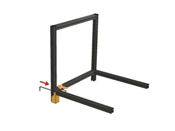
Slide the long side of the hidden L bracket into 460 mm Z-axis extrusion channel.
-
Screw the M8 x 25 mm screw and leave 5mm distance for assembly on the Z-Axis extrusion
-
Slide the 460 mm side extrusion assembly up to the 540 mm extrusion channel. The short side of the hidden L bracket should be inside the 540mm Z-Axis extrusions.
-
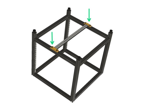
Mount the alignment tool to the bottom of 540mm Extrusion with an M8 x 25 mm screw. Do not overtighten it as it is just to ensure if it fits properly.
-
First, use an M5 Hex Key to tighten the M8 x 25 mm button head screw. Important, do not stoop over the screw to tighten. (Overtightening vertical mount screws causes slight deformation on angles with all Aluminium Extrusions)
-
Then use an M3 Hex Key to tighten the two set screws on the Hidden L brackets. First, slightly tighten one of the set screws and then slightly tighten the second set screw, and then tighten the first one and second one in the same order.
-
-
-
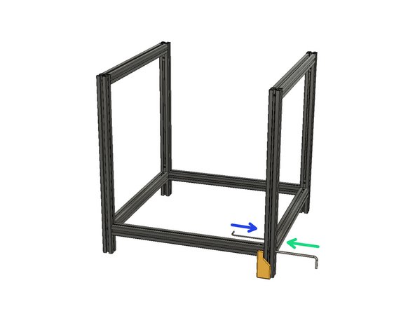
Again, use the 3d printed alignment tool and align the other end of the 460 mm side extrusion and slide it to the 540 mm Z-Axis extrusion channel with M8 x 25 screw and hidden L bracket.
-
Tighten the M8 screw with an M5 hex key. Do nut hulk on these screws. Tighten them but do not over tighten. The hidden L brackets also support the corners.
-
Then use an M3 Hex Key to tighten the two set screws on the hidden L brackets. First, slightly tighten one of the set screws and then slightly tighten the second set screw, and then tighten the first one and second one in the same order.
-
Screw M8 x25 screws and leave a 5mm gap to slide into extrusion channel.
-
Slide the hidden L brackets to 460 mm side extrusions and slide them into 540 mm extrusion channels.
-
Use the M5 hex key to tighten the M8 x 25 screws on both sides. Ensure the 460 mm extrusion is flush with the edges of 540 mm Z-Axis extrusions.
-
Then use an M3 Hex Key to tighten the two set screws on the hidden L brackets on both sides. First, slightly tighten one of the set screws and then slightly tighten the second set screw, and then tighten the first one and second one in the same order.
-
-
-
Please repeat the 1st and 2nd steps and prepare the two sides of the frame.
-
Slide the 460 mm side extrusions as you did in previous steps and use the 3D printed alignment tool again to align side extrusions.
-
Use an M5 hex key to tighten the M8 x 25 screws.
-
Then use an M3 Hex Key to tighten the two set screws on the hidden L brackets on both sides. First, slightly tighten one of the set screws and then slightly tighten the second set screw, and then tighten the first one and second one in the same order.
-
Repeat the second step and tighten the M8 x 25 on the opposite side.
-
Repeat the third step and tighten the screws on the hidden L bracket.
-
-
-
Please be aware Rubber feet, both the natural and synthetic, is not safe to use with vinyl floors because it reacts with the chemicals found in vinyl and causes staining. Heat from sunlight or even the friction of foot traffic on rubber-backed rug pads causes this chemical reaction.
-
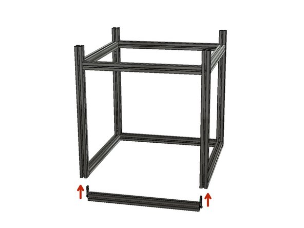
Turn the frame upside down on a flat surface. Slide the remaining side extrusions into the 540 mm Z-Axis extrusions back and front. Make sure that the long side of the hidden L brackets is in 460mm side extrusions. The short side of them should be in 540 mm Z-Axis extrusions.
-
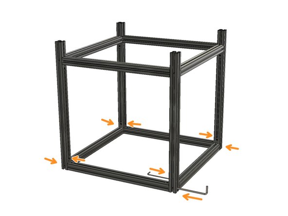
Use an M5 hex key to tighten the M8 x 25 screws and an M3 hex to tighten the hidden L brackets in order as you did in previous steps. Again do not overtighten the M8 screws.
-
Screw the integrated M8 Screws on the rubber feet.
-
-
-
Please be careful with the MGNH Carriages, do not let them come of the rail during assembly. Else the little balls inside will disparkle.
-
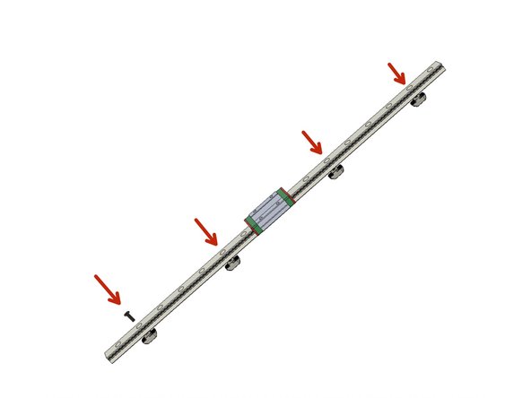
Prepare the 400mm MGN12H Rails by screwing M3 x 8 Countersunk screws to the drop in M3 3030 T-Nuts. Leave a 5mm gap between the rail and the T-Nut. Leave one hole empty from the edges and use the second holes, then use the 6th holes from both edges.
-
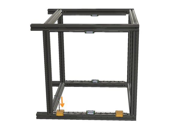
Zaribo Level Cube frame still does not have a direction or orientation yet at this point. You should mount the rails facing each other as seen in the second picture.
-
Use the alignment parts to align the rails on the Z-Axis Extrusions and use an M2 hex key to tighten the countersunk screws. Again you must leave at least 5mm space between the rails and t-Nuts to be able to tighten them properly.
-
-
-
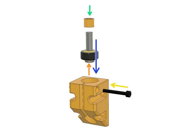
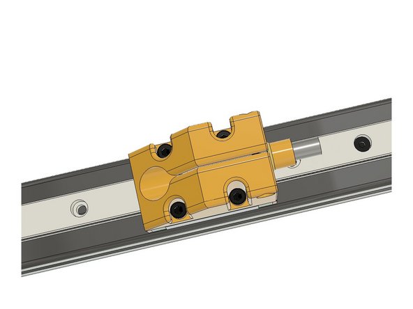
Place the M3 Hex Nut to its place on the Rail Car Carriage part.
-
Insert the M6 x 25 low head screw to Igus Joint bearing.
-
Insert the plastic spacer into the M6 x 25 screw.
-
Place them all together into the carriage.
-
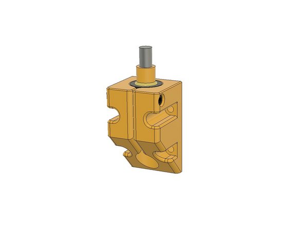
Use the M3 x 22 socket cap screw to tighten the Igus joint bearing in its place.
-
-
-
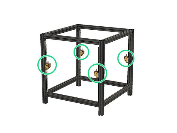
Use four M3 x 10 to mount the carriage on the MGN12H car.
-
Mount the other carriages.
-
-
-
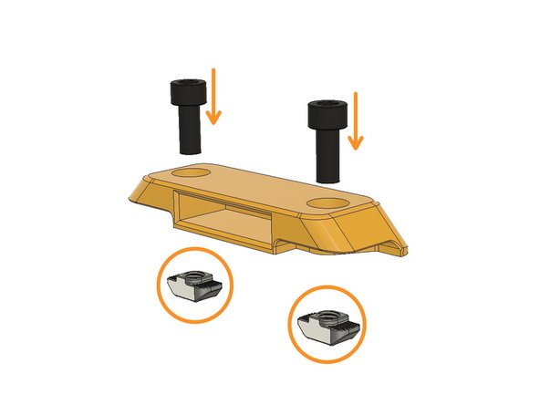
Screw M6 x 12 Socket Cap Screws to M6 3030 drop-in T-nuts and leave 5mm space between the part and the T-Nut
-
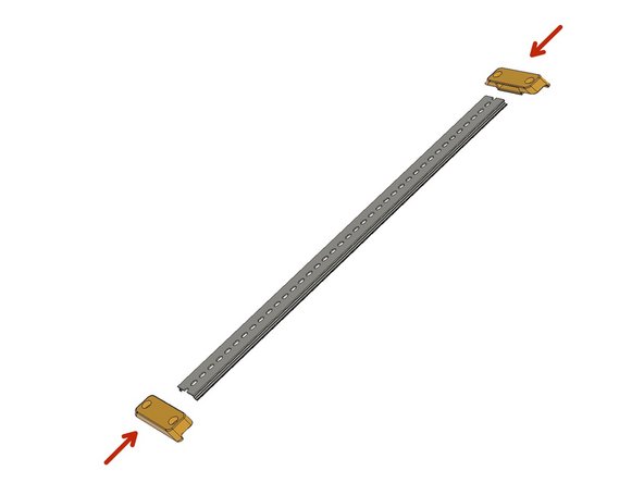
Insert the DIN Rail holders to the DIN rail.
-
Place the DIN Rail in the middle and tighten the M6 screws. Ensure you left at least a 5mm gap between the nut and the Plastic part while tightening. This is the key to make drop-in T-Nuts work.
-


Cancel: I did not complete this guide.
4 other people completed this guide.

One Comment
Guide was easy to follow, pictures helped answer orientation questions.
David Fruehwald - Resolved on Release Reply