
-
-
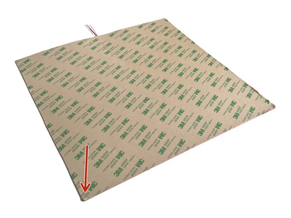
PLEASE REMOVE ANY PROTECTION FILM ON THE BOTH SIDES of ALUMINIUM BED BEFORE INSTALLATION
-
We used a light coloured heated bed illustration to make the instructions more clear and visible.
-
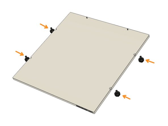
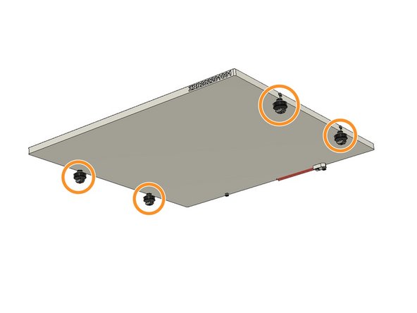
When the topside is up, the serial number should be positioned on the front right edge. Turn the backside of the plate to mount the Fuse and alignment screws supplied in the small plastic bag with the Bed.
-
Screw the M3 x 10mm screw on the right side (from the back view)
-
Screw the Fuse on the other hole with an M3 x 14mm Screw.
-
-
-
In this tutorial, we are going to stick the Magnetic Base Sheet on the Aluminium plate.
-
Peel off the 3M sticker adhesive cover on the Magnetic Base Sheet. Clean the surface of the bed with IPA.
-
Align the adhesive side of the Magnetic Base Sheet on the Aluminium plate by aligning with the M3 screws on top. The Magnetic Base sheet is cut to shape with CNC, so please align the top edges as well. Slowly stick the Magnetic sheet from top to down. Please don't stick the magnetic sheet all at once
-
-
-
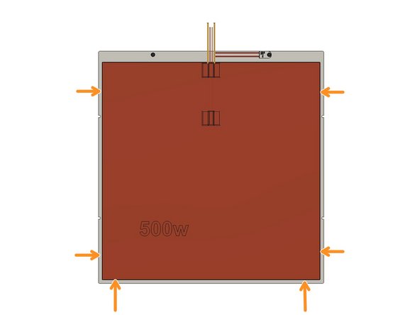
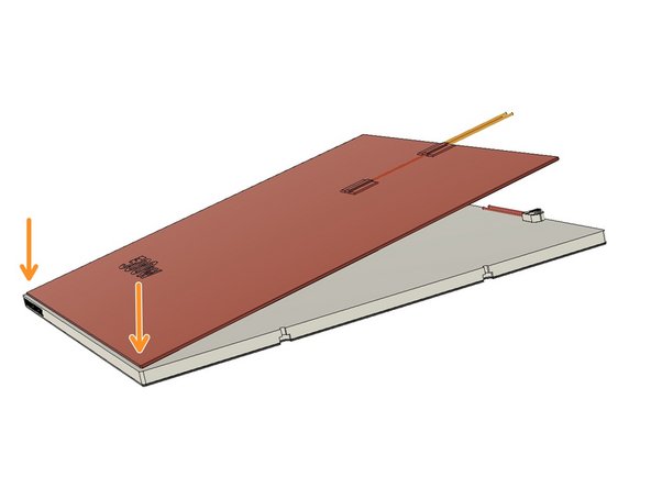
First, peel off the 3M adhesive cover from the Silicone Heating Pad. Turn the back side of the Aluminium Plate up and Clean the surface with IPA.
-
Stick the Silicone Heating Pad on the back of the Aluminium Plate by leaving equal gaps with the sides and the bottom. This time you can start sticking from the bottom side by leaving equal gaps for the sides and bottom edge.
-
-
-
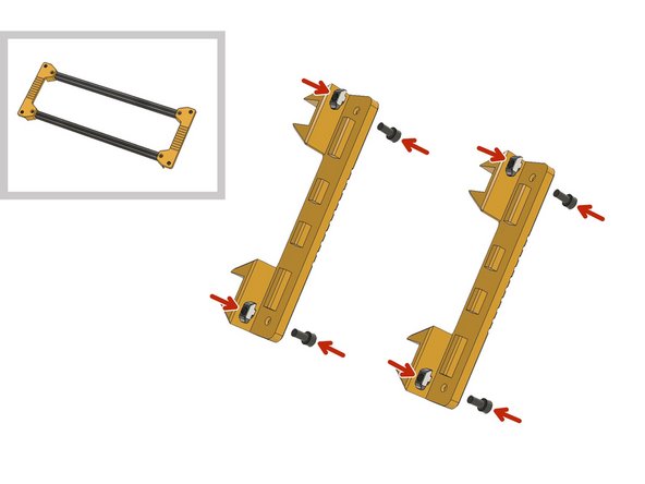
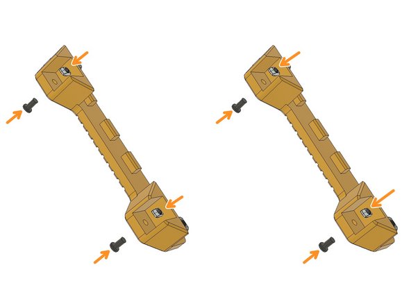
Prepare the Heatbed frame holders with M6 x 12mm and M6 2020 Drop-in T-Nuts. Leave 3mm distance between the nuts and plastic part.
-
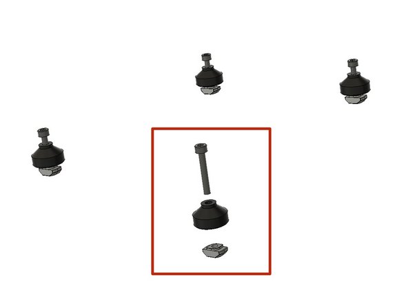
Prepare the M5 x 10mm Ultra-Low Head screws and M5 2020 Drop-in T-Nuts.
-
-
-
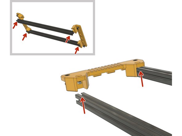
Always ensure that you left enough space for the drop-in nut to turn in the extrusion canal.
-
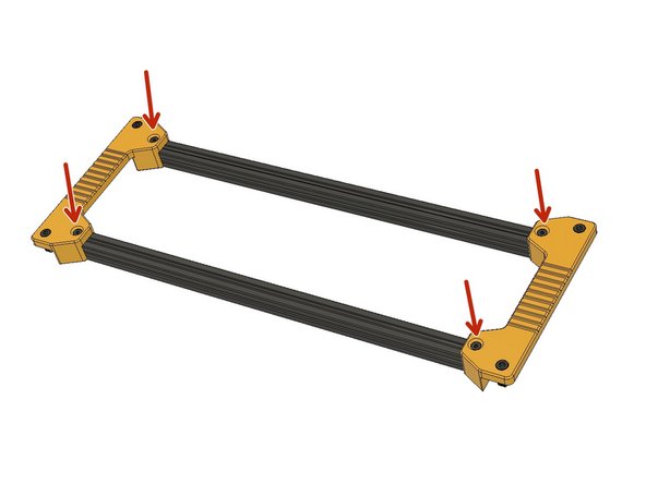
Place the 450mm 2020 Aluminium Extrusions and tighten the M5 x 10mm Ultra-Low Head screws.
-
-
-
Prepare the M3 x20mm screws and 2020 M3 Drop-in T-Nuts.
-
Slide the M3 x 20mm screws on the side slots of the heated bed. (Hold them with your finger when placing them on the heated frame.)
-
-
-
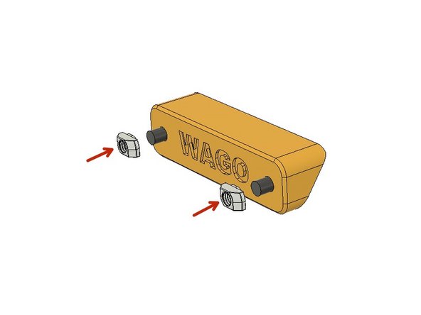
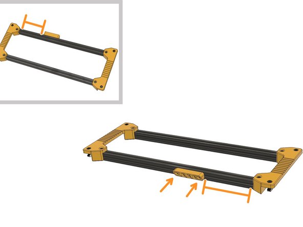
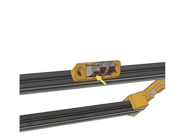
Find the part labelled as WAGO and use M5 2020 Drop-in Nuts and M5 x 10mm Ultra-Low Head screws to prepare the Wago Mount for the assembly.
-
Mount the WAGO housing with a 12cm distance from the side as seen in the picture.
-
Push in the three 2pin WAGO Terminals in the slots.
-
-
-
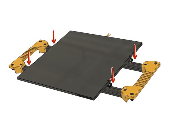
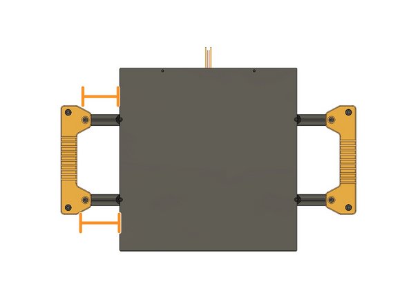
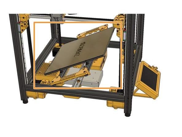
Place the Heated Bed on the bed frame. Insert the Drop-in T-Nuts.
-
Tighten the screws. You can roughly align the bed in the middle by eye sight. You will fine tune the position with the alignment tool when assembling.
-
-
-
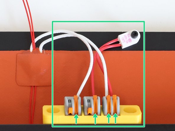
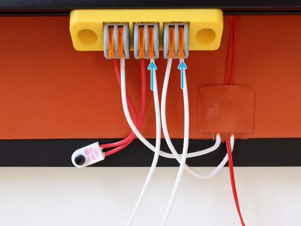
Lift the orange levers on the WAGO Terminals Insert the cables to the holes and lift down the orange levers. Leave the first two left levers open. We will connect the bed mains power to these empty slots.
-
Place the heated bed assembly in an angle and hold it.
-
Insert the supplied mains power cable and lift down the orange levers to lock them in place on the WAGO Terminals.
-
Now, you can put aside the Heated Bed Frame assembly and move on with the following chapter. We will install it after we do the wiring and electronics.
-
-
-
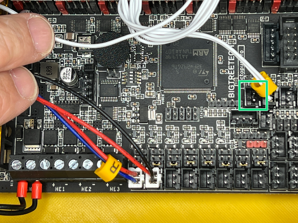
Connect the Heated Bed Thermistor to the left slot of the Hotend Thermistor.
-
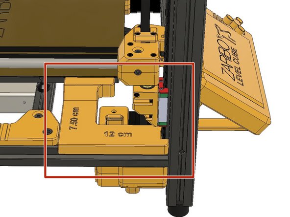
Place the Bed Alignment tool and align the bed. 7.5cm from left side and 12cm from front.
-


Cancel: I did not complete this guide.
3 other people completed this guide.
