
-
-
You can turn the printer upside down or right/left side down to have better and easier access.
-
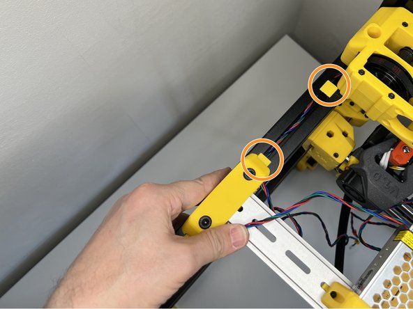
Insert eight Zip Ties into the slots on the sides.
-
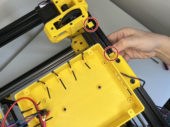
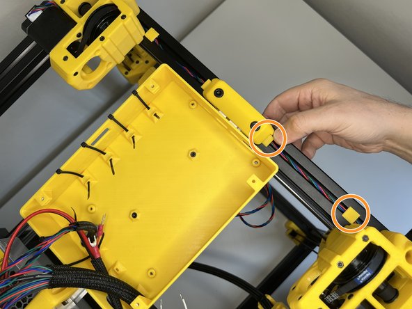
Insert M3 Square Nuts on the body and on the nut holders.
-
Insert two M3 x 10 mm Socket Cap Screws.
-
Screw the M3 x 10 mm Socket Cap Screws while holding the square nut holders behind. These two screws will hold the housing perfectly fine.
-
-
-
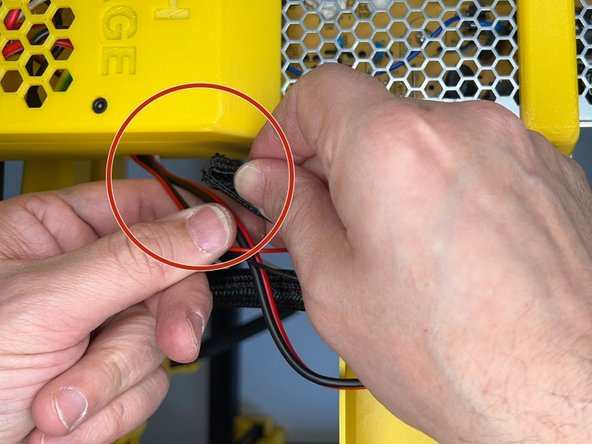
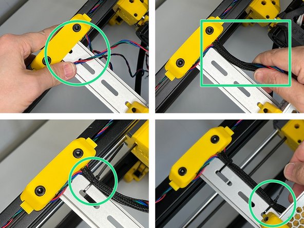
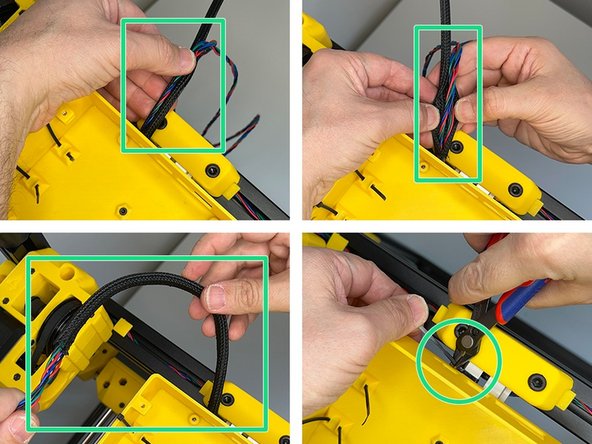
Use the supplied 22cm Thick Sleeve and cover the cables coming from the Z Cable Lift.
-
Pass the cables through the side hole on the controller box.
-
-
-
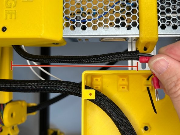
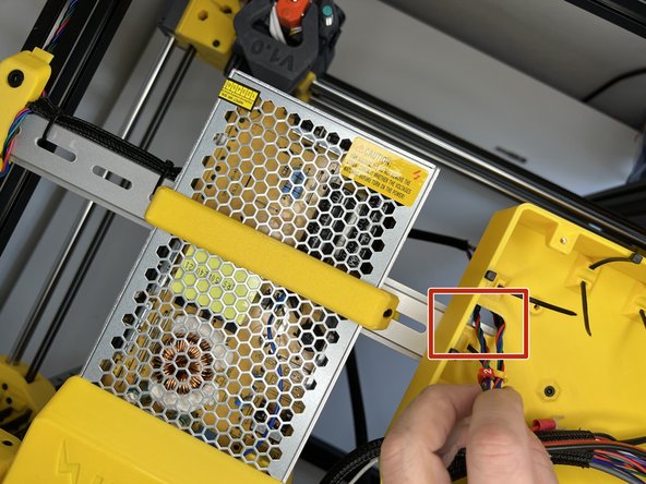
Wrap the power cables from PSU to Mainboard.
-
Pass the cables through the hole on the back of the mainboard box.
-
-
-
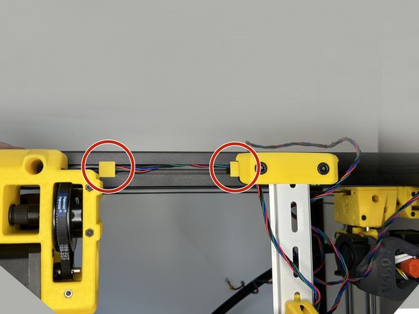
Tuck in the Z Motor 2 cable by using the 3030 cable clips. Pass the cable under the DIN Rail Holder and push the clip in.
-
Do the same with Z Motor 3 Cable.
-
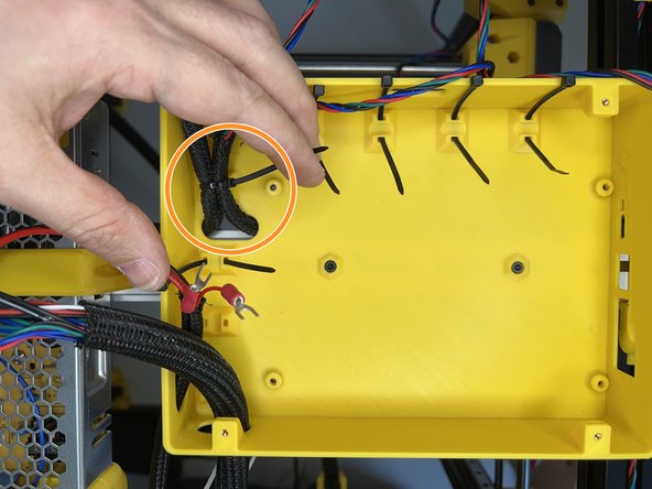
Bring the cables together, tuck them in the 35cm Thin Sleeve and use two zip ties to affix it to the DIN Rail.
-
-
-
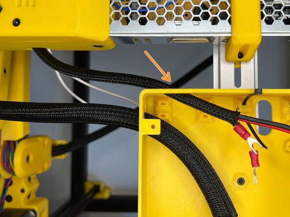
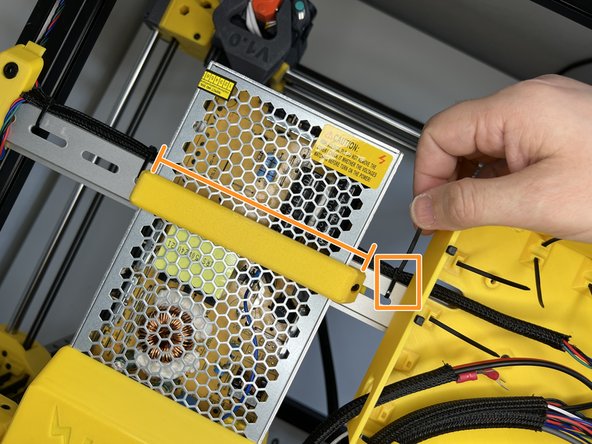
Pass the cables through the hole under the mainboard housing.
-
Pass the sleeve under the PSU. Squeeze the cable sleeve in between the PSU and DIN rail eave and affix it with a zip tie.
-
-
-
Tuck in the Z Motor 4 cable and use the 3030 cable clips to keep them in place. Push the cable and the clip under the DIN Rail holder slot.
-
Do the same with Z Motor 1 Cable.
-
Cover the cables with the 23mm Thin Cable Sleeve and pass them under the mainboard housing. Use a zip tie to affix it to the DIN rail.
-
-
-
Pass the cables through the hole under the mainboard housing.
-
Use the zip tie to fixate the Z motor cables.
-
Connect the power and bed power cables with the supplied jumper cables.
-
-
-
The mainboards shipping with ZLC Kit are coming with necessary jumper settings and the pre-flashed firmware.
-
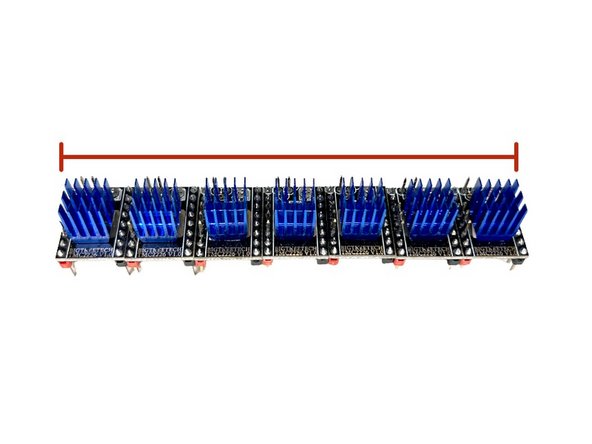
Stick the heat sinks on the stepper motor drivers. Please take extra care with static electricity that can easily ruin the stepper drivers and mainboard.
-
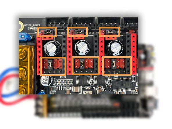
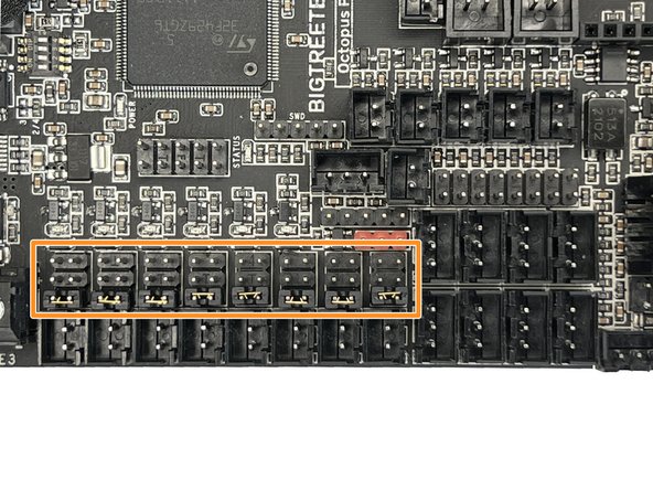
Set the jumpers as seen in the picture for all 8 stepper motor terminals.
-
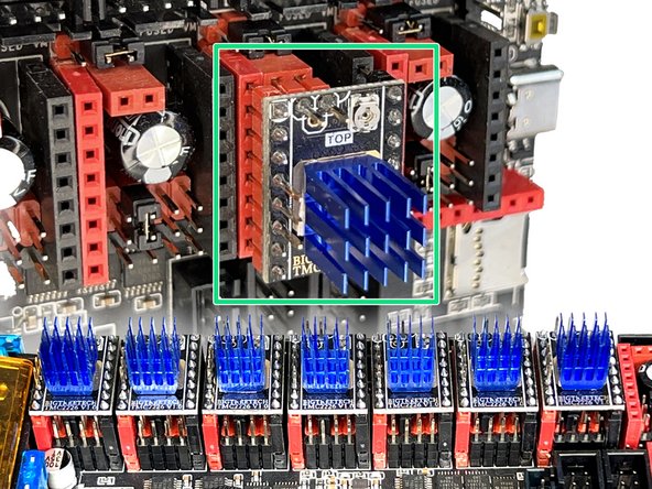
Place the drivers as seen in the picture and push down evenly. The vertical terminals might be slightly spread/wide apart from each other on the Octopus Boards. In that case, slightly insert one side and push slightly towards the necessary direction and align the pins with the terminals.
-
-
-
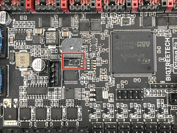
Remove this jumper to be able to flash the firmware through SD Card and leave it off for following Firmware updates.
-
Set the fan jumpers to 24v.
-
-
-
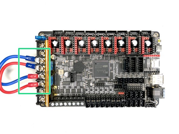
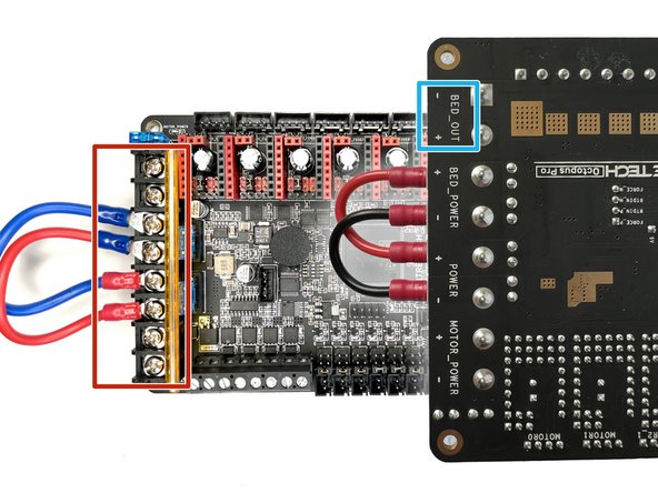
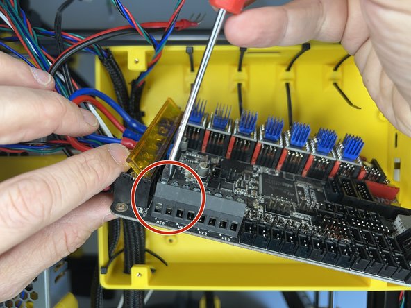
Connect the jumper cables as seen in the pictures. Octopus board needs to get the bed power although it's not going to use it. You are using external mains power with an SSR so this connection is just for the power signal.
-
Connect the bed power cables. Please watch out that the bed power polarisation is adverse with other power connectors on the Octopus board.
-
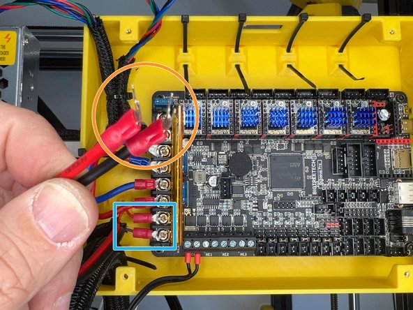
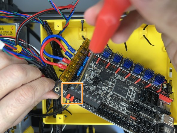
Use a plier and bend the Fork Terminals slightly.
-
Insert the 24v Power terminal forks and tighten the screws.
-
-
-
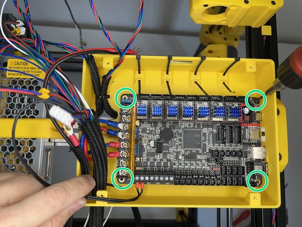
Before fixing the mainboard, loosen the flat screws on the first two terminals for the hotend heater cartridge.
-
Insert the hotend heater cartridge cables and tighten the flat screws.
-
Use four M3 x 8 mm Socket Cap Screws to mount the mainboard.
-
-
-
The cable orders on the connectors are essential for the movement direction of the motors. Please ensure the colours are correctly set on your motor connectors. The 7th Extruder connector might differ according to the motor type on your extruder. For Orbiter, please see the 17th step.
-
Connect motor cables in the order as seen in the picture. 7 is the Extruder Motor. Please see the 17. step for the Orbiter motor connector cable order.
-
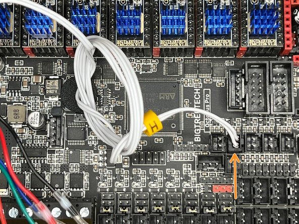
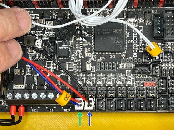
Connect the hotend thermistor cable connector to the slot on the picture. The slot on the left is for the heated bed thermistor.
-
Connect the Radial Fan labelled as R.
-
Connect the Hotend Heatbreak Fan.
-
-
-
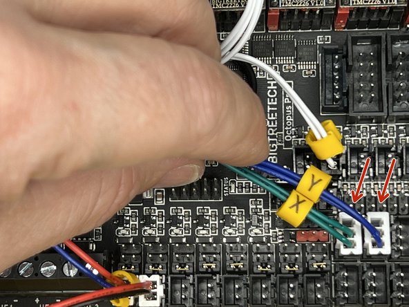
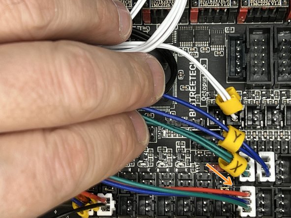
Insert the X and Y Endstop connectors.
-
Insert the Filament Sensor connector.
-
Insert the Inductive Bed Sensor (a.k.a SuperPINDA) connector. The jumper on the right of the terminal should be on for NPN sensors.
-
-
-
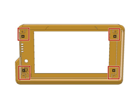
Insert four M3 Square Nuts to the slots on the LCD Housing.
-
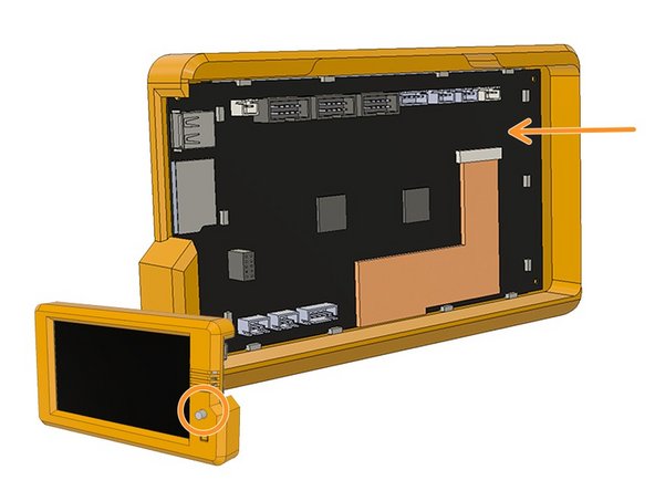
Place the LCD in the housing by aligning the knob with the hole in the front.
-
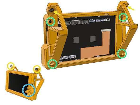
Use four M3 x 20 mm Socket Cap Screws to mount the legs and fix the LCD in the housing.
-
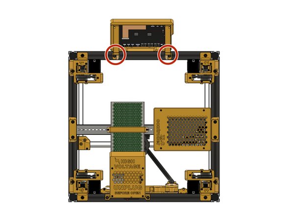
Use two M6 x 12 mm Socket Cap Screws and two M6 3030 Drop-in T-Nuts to prepare the LCD Housing to mount on the frame.
-
Insert the knob and push it all the way in.
-
-
-
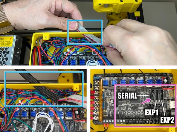
Mount the LCD Controller to the front extrusion.
-
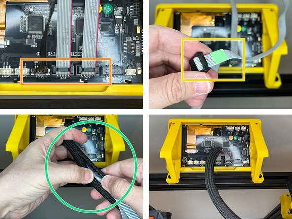
Connect the serial, EXP1 and EXP2 cables.
-
Use a sticker or a marker to mark the EXP2 cable to be able to identify after sleeving.
-
Use the 28cm Thick Sleeve and cover the cables.
-
Pass the cables through the hole on the mainboard housing.
-
Connect the EXP1, EXP2 and Serial cables. The serial terminal has one separate pin for the reset function. The separate pin should be on the arrow marked pin.
-
-
-
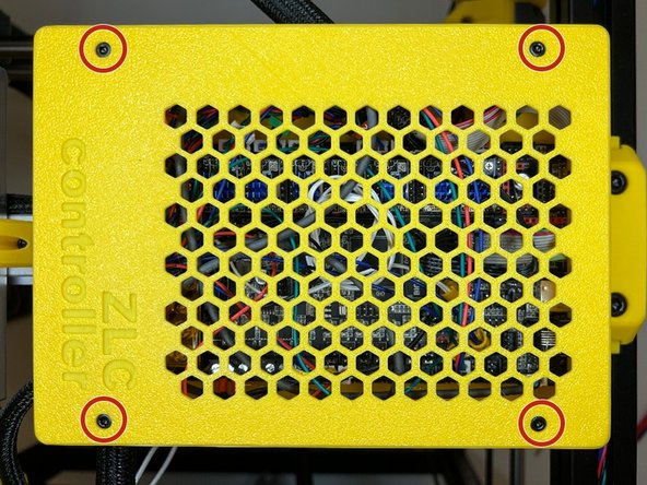
Use four M3 x 10 mm Socket Cap Screws and close the cover of the mainboard housing.
-
-
-
The Orbiter v2 motor connector cable order is different from Zaribo Motors. Please ensure your (7) Extruder motor connector is in the same order as the picture.
-


Cancel: I did not complete this guide.
4 other people completed this guide.
