
-
-
Gantry consists of A-B Motor holders and Y-Axis rod carriages. In this guide, you will be assembling the A and B Motor Drives. A and B Drives each has two plastic parts labelled as Top and Bottom. Always use a longer M3 screw to push M3 nuts in their places and waggle if necessary. This will help you push the nuts all the way in.
-
Insert two M3 Hex nuts on the A BOT(bottom) part for the belt holder.
-
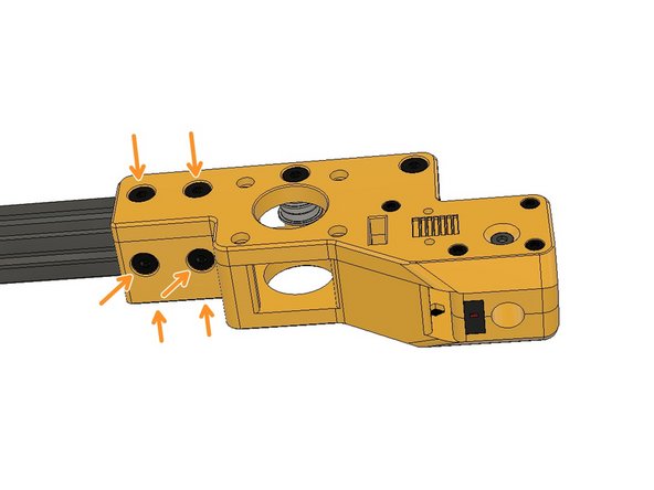
Insert five M3 Hex Nuts on the backside of A BOT part.
-
Insert two M5 Hex Nuts. Again, use an M5 screw to push the nuts all the way in.
-
Insert two M5 x 10 Ultra Low Head Screws.
-
Insert an M6 Square Nut. Use a plier or a screwdriver to push the nut all the way in. Slots are tight on purpose. Please be careful while pushing the nut in and put it on a hard surface while doing it.
-
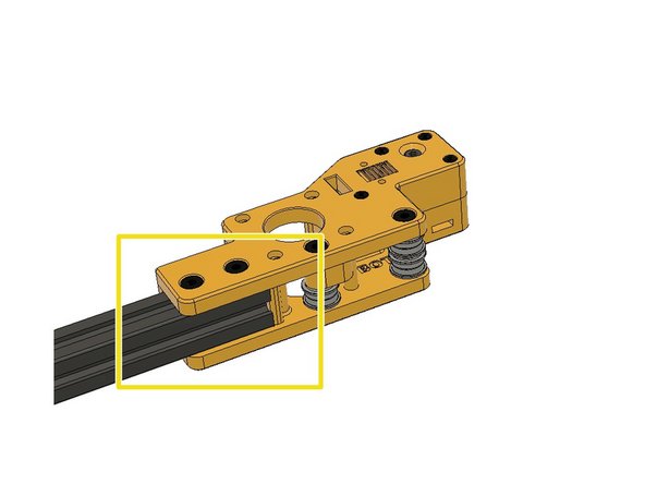
Use M3 x 6mm Socket Cap Screws to fasten the belt holder in its place temporarily. You want to ensure that the M3 Hex nuts behind are properly inserted all the way in.
-
Insert M5 x 10 Ultra Low Head Screws.
-
-
-
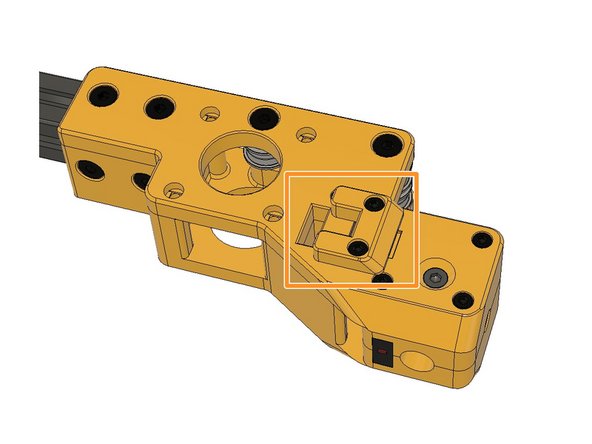
Place the Endstop Y and make sure it is flush with the front surface. tuck in the cable into the canal. The button on the endstop should be upwards.
-
Insert the M5 2020 Drop-in T-Nuts and leave a 4mm gap between the plastic part and the nuts in order to slip the 2020 Extrusions on the following steps.
-
Find the A TOP part, insert two M3 Hex Nuts for the belt lock. Always use a screw to push the nuts in their places to ensure that they went all the way in.
-
Insert two M5 x 10 mm Ultra-Low Head screws and screw the M5 2020 Drop-in T-nuts and leave a 4mm gap between the plastic part.
-
Place the 10mm collet and one of the M4 x 8 mm Low Head Screws to keep it in position. The other hole should be facing the hole on the top.
-
Insert two M5 x 30 mm Ultra-Low Head Screws.
-
Use two M3 x 6 mm Socket Cap Screws and mount the belt lock temporarily to ensure the M3 Hex Nuts are inserted properly.
-
Screw the second M4 x 8 mm Low Head Screw into the collet, do not screw these all the way in. Leave room to insert the rods later.
-
-
-
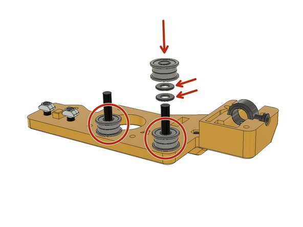
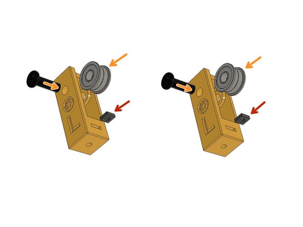
F695zz bearings are used reciprocally to form an idler pulley. Get six F695zz bearings, first, insert two bearings per screw, and then insert two M5 Washers between and insert the other two bearings.
-
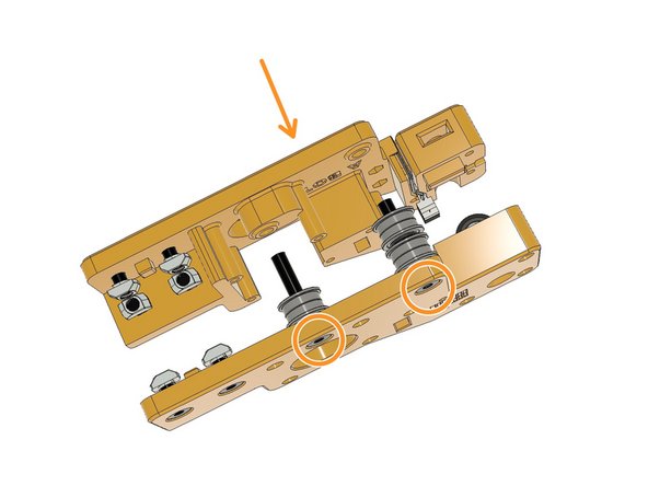
Combine the A TOP and A BOT parts by holding the M5 screw heads with your fingertips. Ensure the endstop cable is not squashed in-between.
-
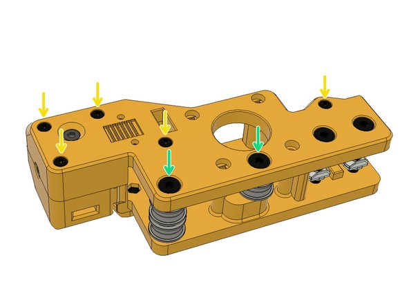
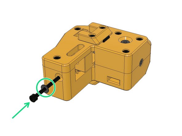
Fasten the five M3 x 30mm Socket Cap Screws to assemble the A TOP and A BOT parts. Remove the temporarily installed belt lock to do so.
-
-
-
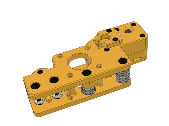
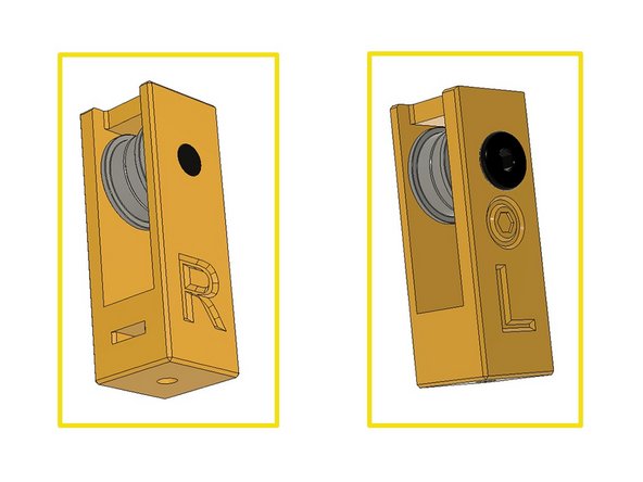
Repeat the same steps for B Drive. It is a mirrored version of A drive. B Drive doesn't have an endstop.
-
-
-
Always use an M3 screw to insert the M3 nuts all the way in and slightly waggle if necessary.
-
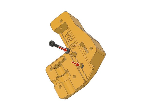
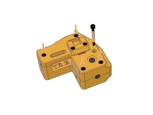
Find the part labelled as YR B which means Y-Axis, Right Bottom. Insert two M3 Hex Nuts all the way in.
-
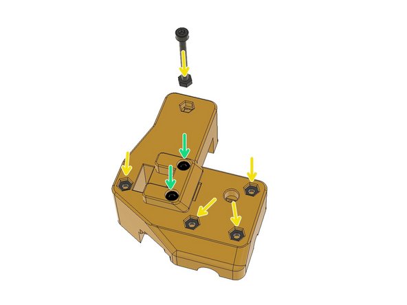
Insert five M3 Hex Nuts on the backside of the YR B part by using the M3 x 30mm screw.
-
Use two M3 x 6mm Socket Cap Screws to fasten the belt lock temporarily to ensure the hex nuts behind are properly inserted. You can keep the belt locks on until you assemble the gantry.
-
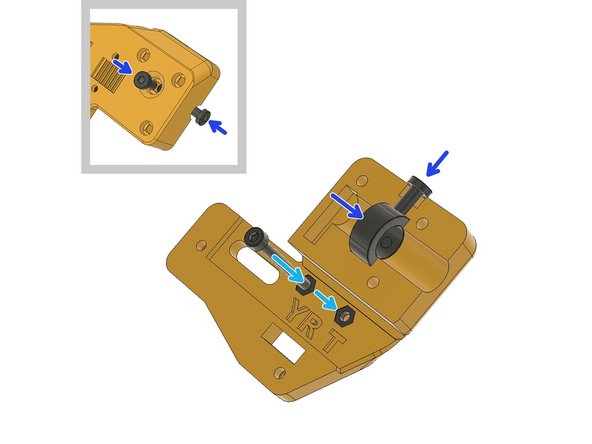
Insert the M3 Hex Nuts to YR T part with the help of an M3 x 30mm screw. Waggle if necessary to push it all the way in.
-
Place the Collet in its place and fasten the M4 x 8mm Low Head screws to secure it. Do not tighten much as we will need to push the 10mm Rod in later.
-
-
-
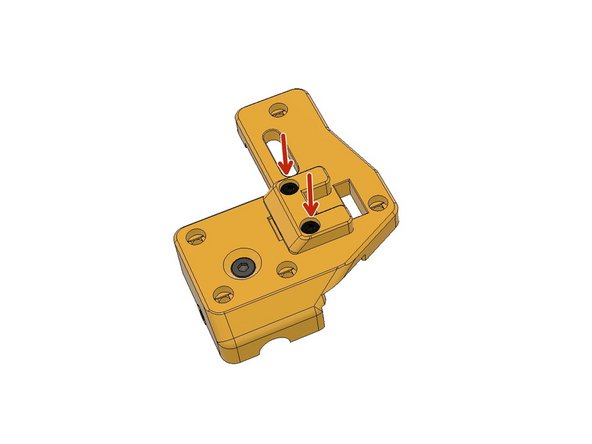
Assemble the belt lock on the YR T part with two M3 x 6mm Socket Cap Screws to ensure the hex nuts behind are properly inserted.
-
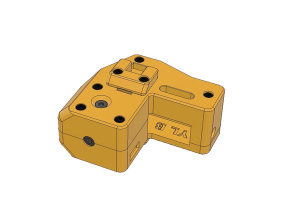
Combine the YR T and YR B parts and fasten the five M3 x 30mm screws. Never overtighten any screws on the printer assembly.
-
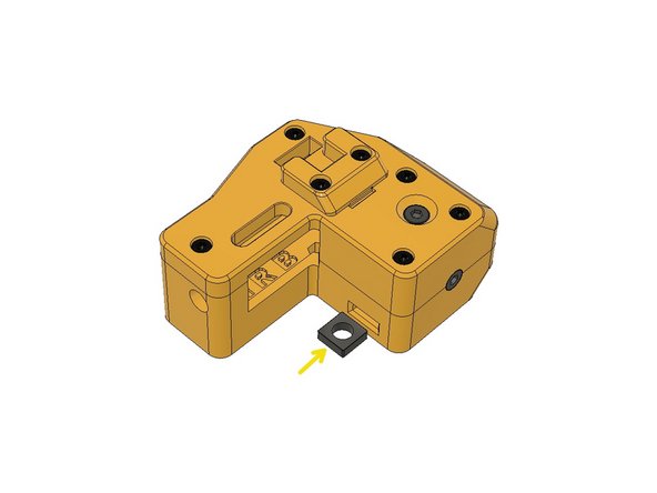
Insert the M6 Square Nut and push it with a flat screwdriver all the way in. Please be careful not to slip the part and sting your hand with a screwdriver.
-
-
-
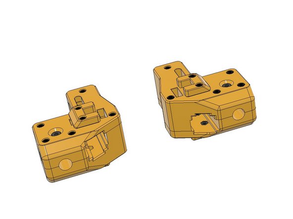
Follow the same steps for YL T and YL B parts.
-
-
-
Get these two Y-axis tensioner parts and Push the M3 Square Nuts all the way in. Use a flat-head screwdriver if necessary to push it in. Our tolerances are tight; please also use a plier to insert the square nut if necessary.
-
Combine the two F695ZZ Bearings and push them in and screw the M5 x 15mm Ultra Low Head Screws as a shaft.
-
Both tensioners are identical. While inserting to Y Carriages you will turn one down and see the correct letter facing upwards. We will be doing this during the belt assembly.
-
Insert an M3 x 30mm Socket Cab Screw with an M3 Washer to temporarily assemble the tensioners.
-
-
-
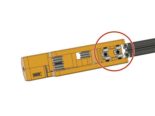
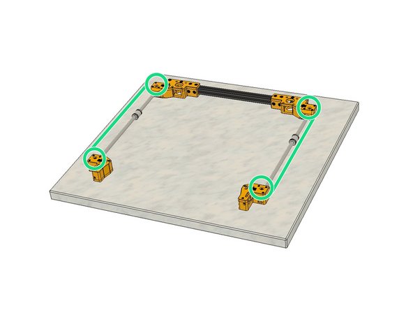
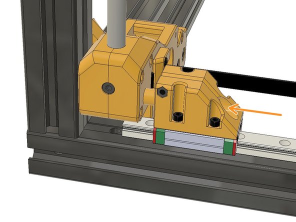
Align the T-Nuts and push the 310mm 2020 extrusion in.
-
Tighten the M5 x 10mm screws. Ensure the screws are flush with the plastic surface before tightening. Drop-in T-Nuts are very useful when you know how to use them properly.
-
Do the same with the B carriage part.
-
-
-
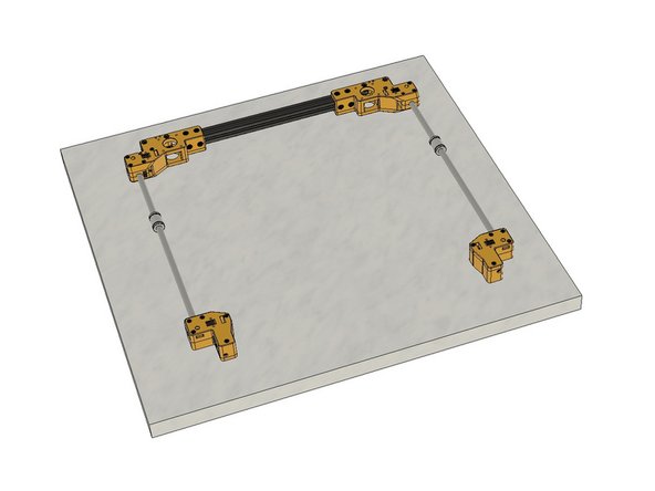
You will use two in this section however soak all four bearings in IPA and let them rest for 25minutes. Then wipe them with a dust-free cloth or paper towel and let them dry before lubing.
-
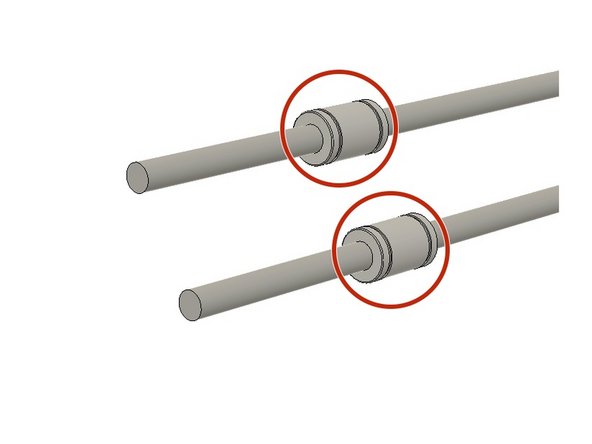
Lube the LMU10 bearings with SuperLube and slide them in along the two rods. Wipe off the excess lube on rod ends. Do not over lube the bearings. Align the bearing and Superlube nozzle while lubing.
-
Now you can unscrew and remove all the belt locks.
-
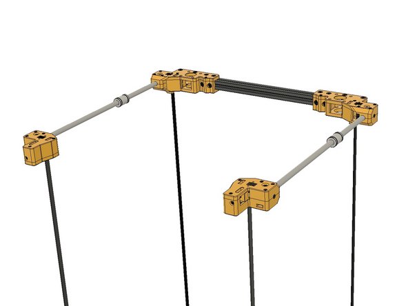
Put the assembly on a flat surface and insert the rods all the way in. Make sure the M4 Collet screws are loose while pushing in. And also loosen the M3 x 30 screws on the Rod side while pushing them in. After ensuring the rods are properly inserted tighten the M4 x 8mm Collet screws and re-tighten all the M3 screws.
-
Do not over tighten M3 screws.
-
-
-
It is easier to install the 9mm Z-Axis belt ends at this stage. Turn the gantry assembly upside down and put it on a flat surface to install one end of the Z-Axis Belts. If you cannot find any flat surface you can put it on the top of the printer frame.
-
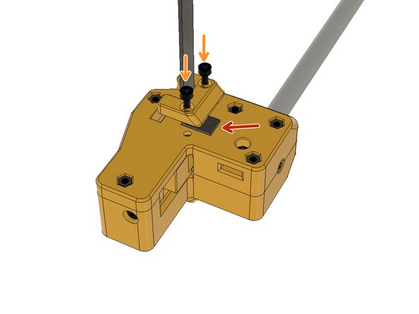
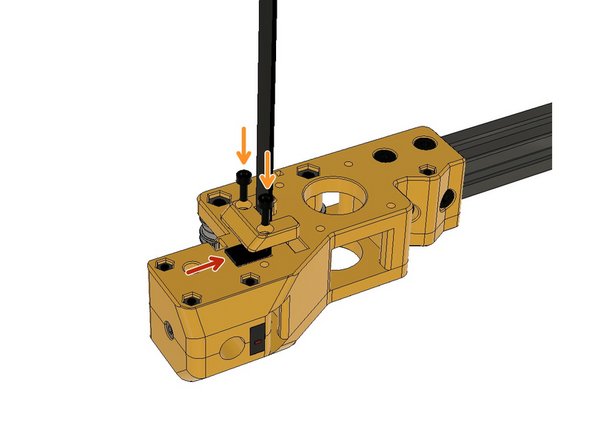
Place the 100cm 9mm belt end on the back of the Y carriages. You will see the grooves which should interlace with the belt teeth so the teeth of the belt should be facing toward these grooves. You can slightly scrape off the groove edges if necessary due to elephant foot effect on 3d printed parts.
-
Tighten the belt locks with M3 x 6 Socket Cap Screws to fasten the 9mm Z-Axis Belt ends.
-
Do this on each corner and lock all four Z-Axis belts on the bottom side of the Gantry Carriages.
-
-
-
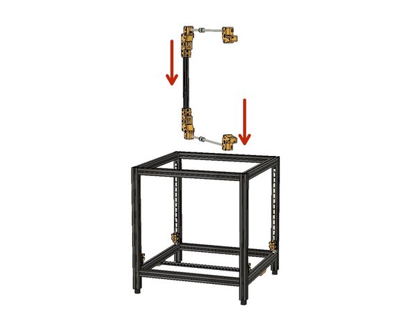
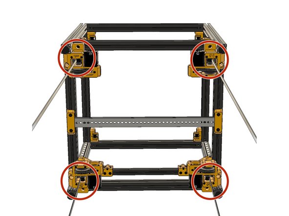
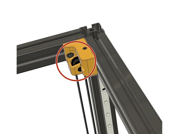
Now you are ready to put the Gantry on the Z-Axis carriages.
-
Insert the Gantry in a transverse angle into the frame.
-
-
-
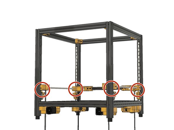
Align the M6 screws on the Z carriages with the holes beneath the Gantry Corners.
-
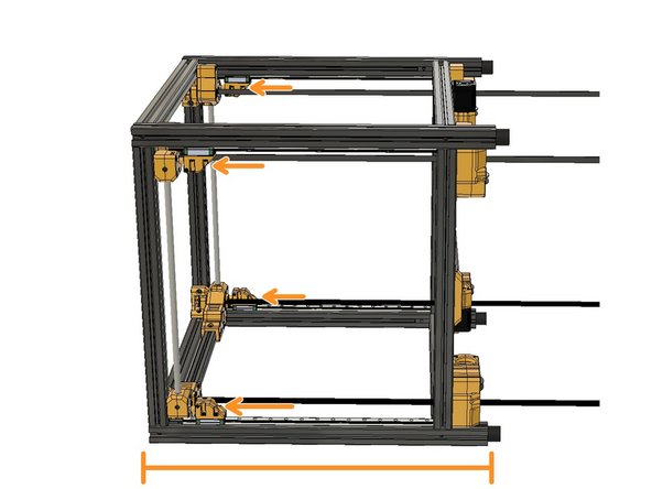
Turn the frame back side down. And use an M5 Hex Key to tighten the Z Carriage screws.
-
-
-
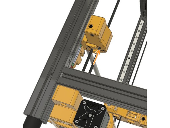
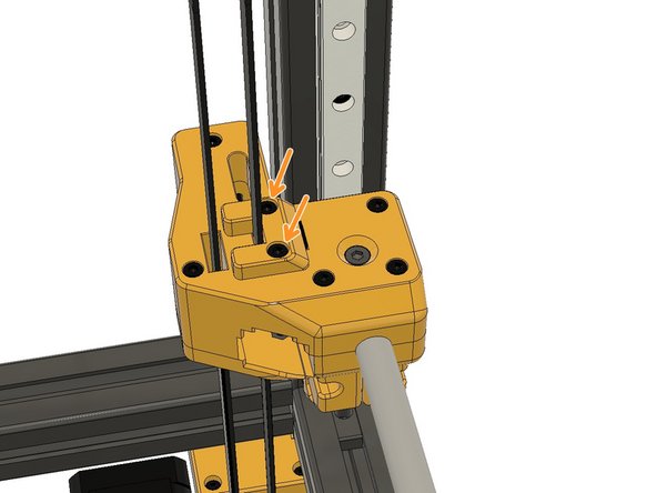
Pass the 9mm Z-Axis belts around the GT2 9mm Pulleys on the Z-Axis Motor assembly.
-
Pass the belt through the canals on the Y and A B Carriages.
-
-
-
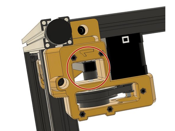
Pass the belt through the Top Z-Axis Tensioners on the corners.
-
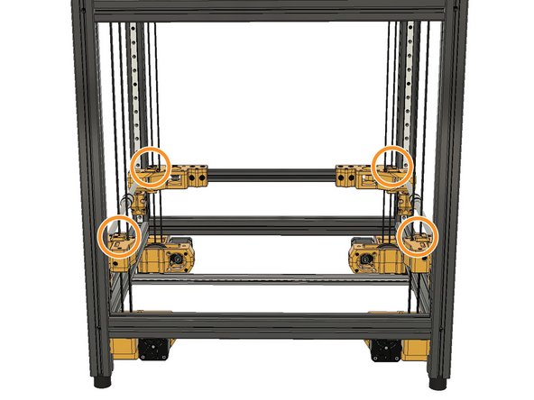
Fasten the belts with the belt locks on all carriages. Remove the top Z Tensioner pulleys from their places if necessary to be able to lock the belts easily.
-
Tune all four Z belts to 80Hz with a
-
-
-
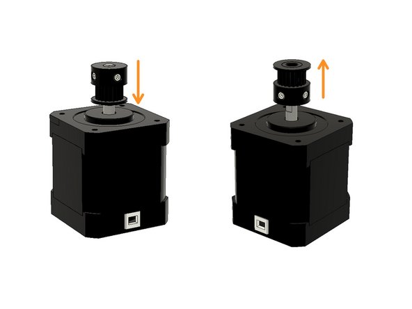
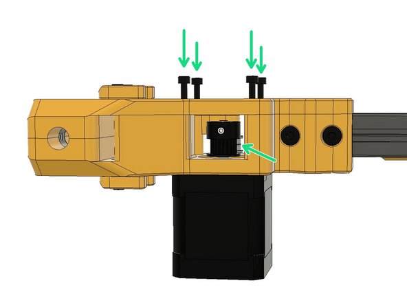
Insert GT2 20T Pulleys as seen in the picture. The B motor pulley on the left should be upside down. You can temporarily tighten one of the set screws to keep them in place while assembling.
-
Mount the motor with M3 x 35mm Socket Cap Screws. The motor cable connector should be facing backwards.
-
Align the A Motor Pulley with the idler bearing behind, as seen in the picture, and tighten the pulley set screws.
-
Do the same with the B motor and mount it with M3 x 35mm Socket Cap Screws, but this time, the pulley should be upside down and aligned with the idler bearings at the bottom side.
-


Cancel: I did not complete this guide.
3 other people completed this guide.
