
-
-
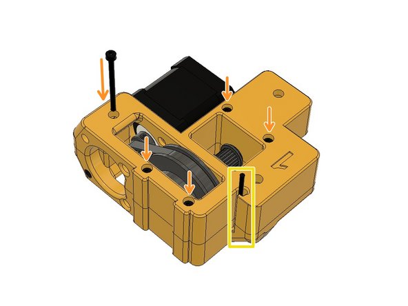
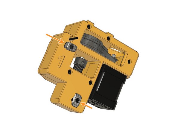
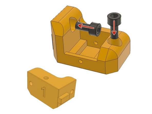
Insert M3 nuts on the part labelled as 1. Use the M3 x 40mm screws to push the nut in its place till the end. (1 and 3 are the same designs, 2 and 4 are mirror designs of 1 and 3)
-
Place the motor as seen in the picture. The motor connector should be facing down.
-
Mount the Zaribo Motor with M3 x 35mm and M3 x 8mm screws. You can tighten the 8mm screw through the hole in the front.
-
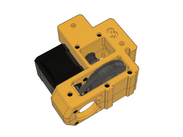
Insert the 16T GT2 Timing Pulley to the motor shaft and slightly tighten one of the set screws just to keep it in its place for now.
-
-
-
Insert the components on the 60mm x 5mm D-Shaft in the order seen in the picture. From left to right: F695ZZ, GT2 20T 9mm Pulley, F695ZZ, GT2 80T 6mm Pulley, F695ZZ (reversed). Do not tighten the pulleys yet.
-
Slip on the 188mm loop belt over the motor pulley and place the shaft assembly in its place carefully. F695ZZ Bearing flanges should seat on the slots.
-
-
-
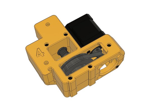
Align the 80T Pulley and 16T Motor Pulley. Leave equal spaces on the sides of the 80T pulley and align the belt and motor pulley. Tighten the set screws on the pulleys to fix them on the shafts. (do not tighten the set screws on 20T 9mm Pulley for now)
-
Tuck the motor cable into the cable canal. Ensure the cable connected to the motor while doing it.
-
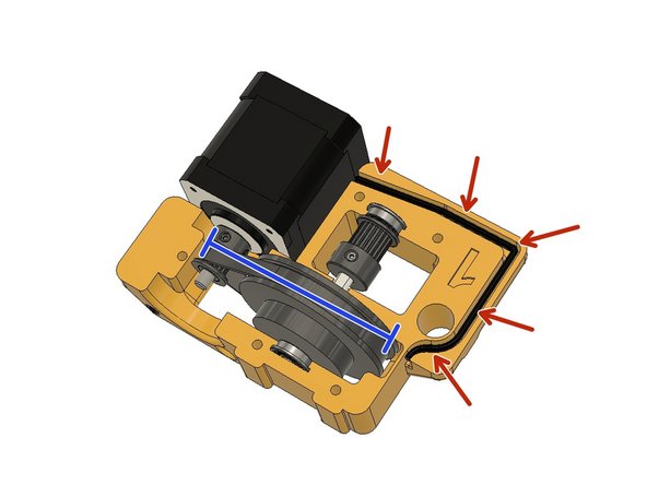
Cover the assembly with the second part labelled as 1 and pass the motor cable through the canal.
-
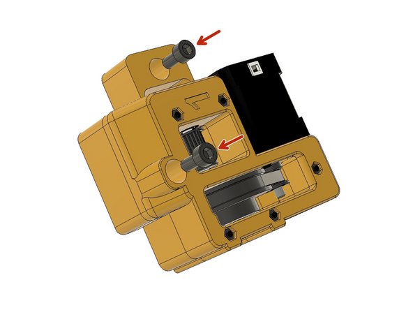
Use M3 x 40mm screws and tighten them to assemble the geared Z Motor housing.
-
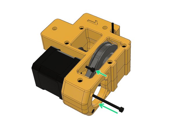
Use M3 x 8mm and M3 x 35mm screws to tighten the motor to finalise the Z Motor assembly. Placing the 8mm screw can be a little tricky. You can push the loop belt slightly to place the 8mm screw. You can tighten this screw through the hole in the front.
-
-
-
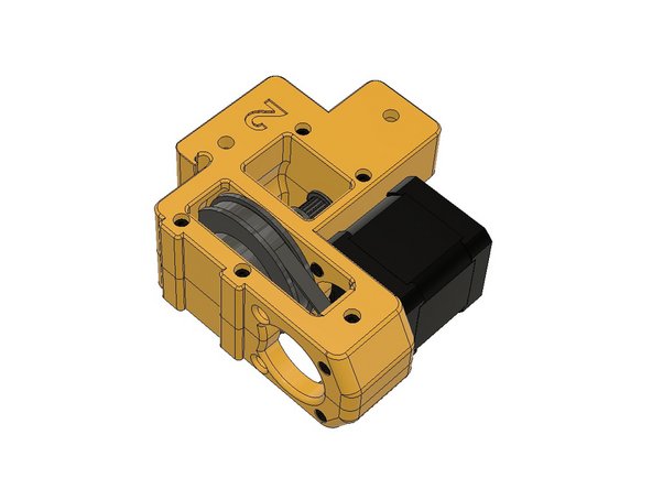
Now you successfully assembled Z1 motor. Please follow the same steps with 2, 3 and 4th motors. The same designs, just mirrored.
-
-
-
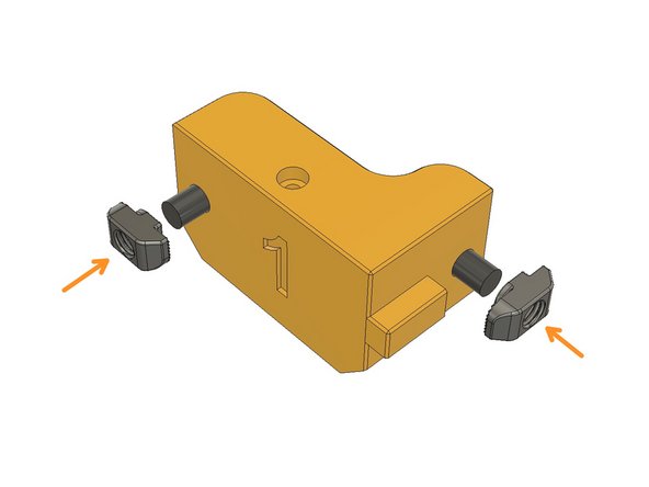
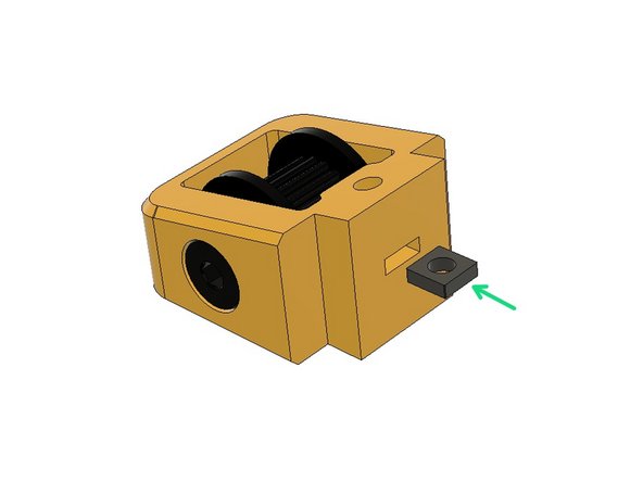
Insert M6 x 12 mm screws in the holes seen in the picture.
-
Screw the 3030 M6 T-Nuts and leave 5mm gap between the plastic part.
-
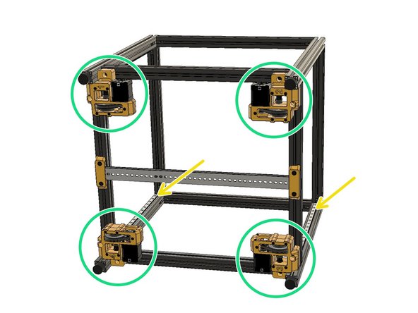
Until this point, the frame didn't have a front or a back orientation. Now you set the orientation of your frame while mounting the Z Motor assemblies. Ensure the rails are facing as seen.
-
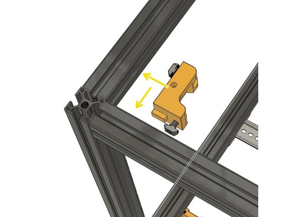
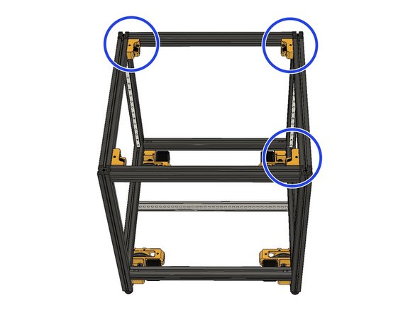
Mount the Z Motor assemblies in the same order as seen in the picture. The pre-insert T-Nuts are very handy however you need to leave 5mm space before tightening.
-
Coiling the Z Motor cables might be helpful at this stage in order to move the printer without tangling with the Z Motor cables.
-
-
-
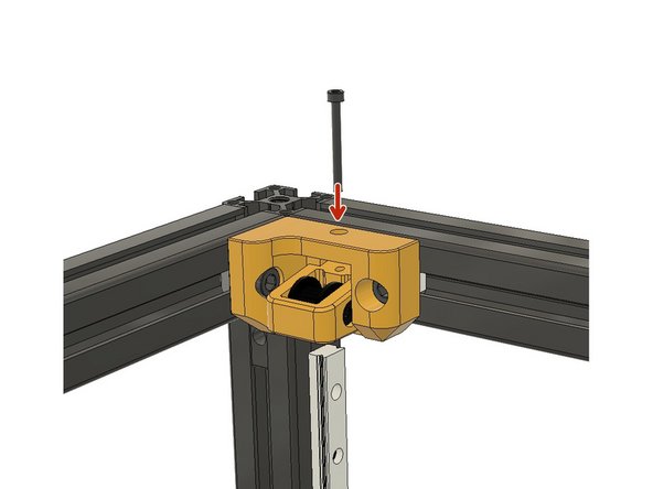
Insert M6 x 12mm screws and make sure you slide them all the way in. The holes can be a bit narrow so you can use a screwdriver to screw them in.
-
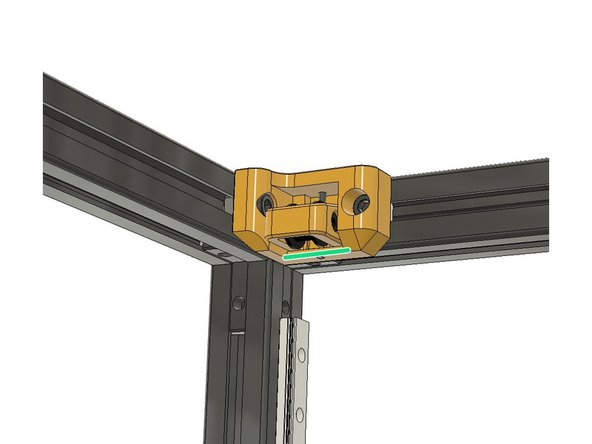
Screw the M6 3030 Drop-in T-Nuts and leave 5mm space between the plastic part and the nut.
-
Place the tensioner on top of the Z Motor holder. Ensure the part numbers are correctly aligned same as the Z Motor assemblies.
-
-
-
Z Motor assemblies and Z top tensioners should be aligned in 1,2,3,4 order as seen in the picture.
-
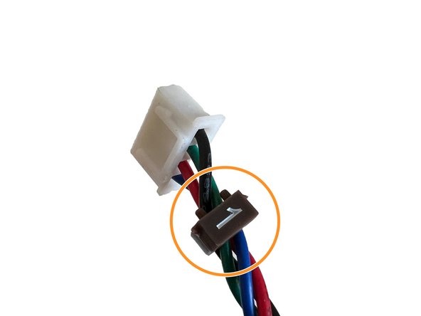
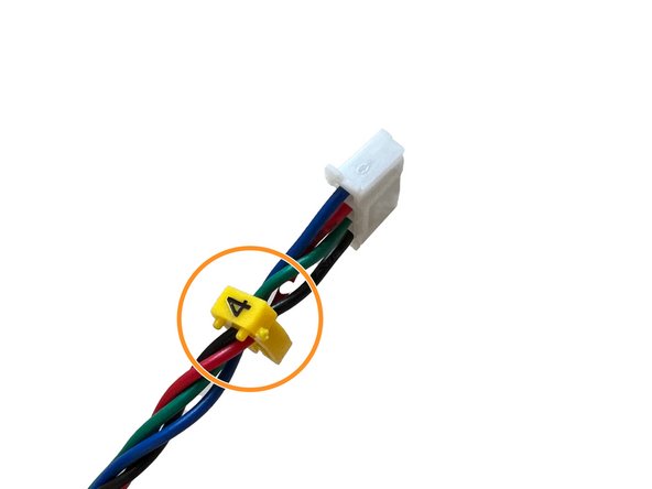
Use the provided cable clips to mark the motor cables as 1,2,3,4 which will be useful while connecting the connectors on the controller board.
-
-
-
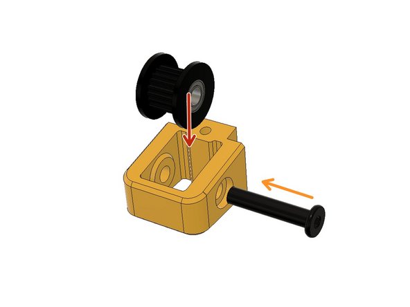
Insert the 9mm toothed idler and hold it aligned with the holes.
-
Screw the M5 x 25mm ultra-low head screw in.
-
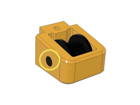
Ensure the screw end is flush with the side of the pulley holder. Do not tighten more.
-
Insert an M3 square nut into the idler pulley holder. Our tolerances are tight; please use a plier to insert the square nut if necessary.
-
-
-
Use an M3 x 30mm socket cap screw to fix the tensioner assembly in its place.
-
Leave the tensioner at its lowest position.
-
Follow the same steps for 2,3,4.
-


Cancel: I did not complete this guide.
2 other people completed this guide.
